A Look at ECG Recordings
The heart’s electrical activity produces currents that radiate through the surrounding tissue to the skin. When electrodes are attached to the skin, they sense those electrical currents and transmit them to an ECG monitor. The currents are then transformed into waveforms that represent the heart’s depolarization–repolarization cycle.
You might remember that myocardial depolarization occurs when a wave of stimulation passes through the heart and stimulates the heart muscle to contract. Repolarization is the return to the resting state and results in relaxation.
An ECG shows the precise sequence of electrical events occurring in the cardiac cells throughout that process. It allows the nurse to monitor phases of myocardial contraction and to identify rhythm and conduction disturbances. A series of ECGs can be used as a baseline comparison to assess cardiac function.
Leads and Planes

To understand electrocardiography, you need to understand leads and planes. Electrodes placed on the skin measure the direction of electrical current discharged by the heart. This current is then transformed into waveforms.
An ECG records information about those waveforms from different views or perspectives. These perspectives are called leads and planes.
Take the Lead
A lead provides a view of the heart’s electrical activity between one positive pole and one negative pole. Between the two poles lies an imaginary line representing the lead’s axis, a term that refers to the direction of the current moving through the heart.
The direction of the current affects the direction in which the waveform points on an ECG. (See Current direction and wave deflection.) When no electrical activity occurs or the activity is too weak to measure, the waveform looks like a straight line, called an isoelectric waveform.
Plane and Simple
The term plane refers to a cross-sectional perspective of the heart’s electrical activity. The frontal plane, a vertical cut through the middle of the heart, provides an anterior-to-posterior view of electrical activity. The horizontal plane, a transverse cut through the middle of the heart, provides either a superior or an inferior view.
Types of ECGs
The two types of ECG recordings are the 12-lead ECG and a rhythm strip. Both types give valuable information about heart function.
A Dozen Views
A 12-lead ECG records information from 12 different views of the heart and provides a complete picture of electrical activity. These 12 views are obtained by placing electrodes on the patient’s limbs and chest. The limb leads and the chest, or precordial leads, reflect information from different planes of the heart.
Different leads provide different information. The six limb leads—I, II, III, augmented vector right (aVR), augmented vector left (aVL), and augmented vector foot (aVF)—provide information about the heart’s frontal (vertical) plane. Leads I, II, and III require a negative and positive electrode for monitoring, which makes the leads bipolar. The augmented leads record information from one lead and are called unipolar.
The six precordial or V leads—V1, V2, V3, V4, V5, and V6—provide information about the heart’s horizontal plane. Just like the augmented leads, the precordial leads are also unipolar, requiring only a single electrode. The opposing pole of these leads is the center of the heart as calculated by the ECG.
Just One View
A rhythm strip, which can be used to monitor cardiac status, provides information about the heart’s electrical activity from one or more leads simultaneously. Chest electrodes pick up the heart’s electrical activity for display on the monitor. The monitor also displays heart rate and other measurements and allows for printing strips of cardiac rhythms.
Commonly monitored leads include the bipolar leads I, II, III, MCL1, and MCL6 as well as unipolar leads V1 and V6. The acronym MCL stand s for modified chest lead. These leads are similar to the unipolar leads V1 and V6 of the 12-lead ECG. MCL1 and MCL6, however, are bipolar leads.
Monitoring ECGs
The type of ECG monitoring system you’ll use—hardwire monitoring or telemetry—depends on the patient’s condition and where you work. Let’s look at each system.
Hardwire Basics

With hardwire monitoring, the electrodes are connected directly to the cardiac monitor. Most hardwire monitors are mounted permanently on a shelf or wall near the patient’s bed. Some monitors are mounted on an IV pole for portability, and some may include a defibrillator.
The monitor provides a continuous cardiac rhythm display and transmits the ECG tracing to a console at the nurses’ station. Both the monitor and the console have alarms and can print rhythm strips. Hardwire monitors can also track pulse oximetry, blood pressure, hemodynamic measurements, and other parameters through various attachments to the patient.
Some Drawbacks
Hardwire monitoring is generally used in intensive care units and emergency departments because it permits continuous observation of one or more patients from more than one area in the unit. However, this type of monitoring does have drawbacks, among them:
- limited patient mobility because the patient is tethered to a monitor by a cable
- patient discomfort because the electrodes and cables are attached to the chest
- possibility of lead disconnection and loss of cardiac monitoring when the patient moves.
Portable Points
Telemetry monitoring is generally used in step-down units and medical–surgical units where patients are permitted more activity. With telemetry monitoring, the patient carries a small, battery-powered transmitter that sends electrical signals to another location where the signals are displayed on a monitor screen. This type of ECG monitoring frees the patient from cumbersome wires and cables associated with hardwire monitoring.
Telemetry monitoring still requires skin electrodes to be placed on the patient’s chest. Each electrode is connected by a thin wire to a small transmitter box carried in a pocket or pouch. It’s especially useful for detecting arrhythmias that occur with activity or stressful situations. Most systems, however, can monitor heart rate and rhythm only.
All About Leads

Electrode placement is different for each lead, and different leads provide different views of the heart. A lead may be chosen to highlight a particular part of the ECG complex or the electrical events of a specific cardiac cycle. Ongoing biomedical research tests for best lead placement for the best result.
Although leads II, V1, and V6 are among the most commonly used leads for monitoring, you should adjust the leads according to the patient’s condition. If your monitoring system has the capability, you may also monitor the patient in more than one lead.
Going to Ground
All bipolar leads have a third electrode, known as the ground, which is placed on the chest to prevent electrical interference from appearing on the ECG recording.
Here is Lead 1
Lead I provides a view of the heart that shows current moving from right to left. Because current flows from negative to positive, the positive electrode for this lead is placed on the left arm or on the left side of the chest; the negative electrode is placed on the right arm. Lead I produces a positive deflection on ECG tracings and is helpful in monitoring atrial rhythms and hemiblocks.
Introducing Lead II
Lead II produces a positive deflection. Place the positive electrode on the patient’s left leg and the negative electrode on the right arm. For continuous monitoring, place the electrodes on the torso for convenience, with the positive electrode below the lowest palpable rib at the left midclavicular line and the negative electrode below the right clavicle. The current travels down and to the left in this lead. Lead II tends to produce a positive, high-voltage deflection, resulting in tall P, R, and T waves. This lead is commonly used for routine monitoring and is useful for detecting sinus node and atrial arrhythmias.
Next Up, Lead III
Lead III produces a positive deflection. The positive electrode is placed on the left leg, and the negative electrode is placed on the left arm. Along with lead II, this lead is useful for detecting changes associated with an inferior wall myocardial infarction.
The axes of the three bipolar limb leads—I, II, and III—form a triangle around the heart and provide a frontal plane view of the heart. (See Einthoven’s triangle.)
The “a” Leads
Leads aVR, aVL, and aVF are called augmented leads because the small waveforms that normally would appear from these unipolar leads are enhanced by the ECG. (See Augmented leads) The “a” stand s for “augmented,” and “R, L, and F” stand for the positive electrode position of the lead.
In lead aVR, the positive electrode is placed on the right arm (hence, the R) and produces a negative deflection because the heart’s electrical activity moves away from the lead. In lead aVL, the positive electrode is on the left arm and produces a positive deflection on the ECG. In lead aVF, the positive electrode is on the left leg (despite the name aVF where the F refers to “foot”) and produces a positive deflection. These three limb leads also provide a view of the heart’s frontal plane.
The Preeminent Precordials
The six unipolar precordial leads are placed in sequence across the chest and provide a view of the heart’s horizontal plane. (See Precordial views.) These leads include:
- Lead V1: The precordial lead V1 electrode is placed on the right side of the sternum at the fourth intercostal rib space. This lead corresponds to the modified chest-lead MCL1 and shows the P wave, QRS complex, and ST segment particularly well. It helps to distinguish between right and left ventricular ectopic beats that result from myocardial irritation or other cardiac stimulation outside the normal conduction system. Lead V1 is also useful in monitoring ventricular arrhythmias, ST-segment changes, and bundle-branch blocks.
- Lead V2: Lead V2 is placed at the left of the sternum at the fourth intercostal rib space.
- Lead V3: Lead V3 goes between V2 and V4. Leads V1, V2, and V3 are biphasic, with both positive and negative deflections. Leads V2 and V3 can be used to detect ST-segment elevation.
- Lead V4: Lead V4 is placed at the fifth intercostal space at the midclavicular line and produces a biphasic waveform.
- Lead V5: Lead V5 is placed at the fifth intercostal space at the anterior axillary line. It produces a positive deflection on the ECG and , along with V4, can show changes in the ST segment or T wave.
- Lead V6: Lead V6, the last of the precordial leads, is placed level with V4 at the midaxillary line. This lead produces a positive deflection on the ECG.
The Modest Modified Lead
MCL1 is similar to lead V1 on the 12-lead ECG and is created by placing the negative electrode on the left upper chest, the positive electrode on the right side of the sternum at the fourth intercostal space, and the ground electrode usually on the right upper chest below the clavicle.
When the positive electrode is on the right side of the heart and the electrical current travels toward the left ventricle, the waveform has a negative deflection. As a result, ectopic or abnormal beats deflect in a positive direction.
You can use this lead to monitor premature ventricular contractions and to distinguish different types of tachycardia, such as ventricular tachycardia and supraventricular tachycardia. Lead MCL1 can also be used to assess bundle-branch defects and P-wave changes and to confirm pacemaker wire placement.
A Positive Option
MCL6 may be used as an alternative to MCL1. Just like MCL1, it monitors ventricular conduction changes. The positive lead in MCL6 is placed in the same location as its equivalent, lead V6. The positive electrode is placed at the fifth intercostal space at the midaxillary line, the negative electrode below the left shoulder, and the ground below the right shoulder.
Electrode Basics
A three- or five-electrode (or leadwire) system may be used for cardiac monitoring. (See Leadwire systems.) Both systems use a ground electrode to prevent accidental electrical shock to the patient.

A three-electrode system has one positive electrode, one negative electrode, and a ground.
The popular five-electrode system uses an exploratory chest lead to monitor any six modified chest leads as well as the stand ard limb leads. (See Using a five-leadwire system) This system uses stand ardized chest placement. Wires that attach to the electrodes are usually color-coded to help you to place them correctly on the patient’s chest.
Another application of bedside cardiac monitoring is a reduced lead continuous 12-lead ECG system (EASI* system), which uses an advanced algorithm and only five electrodes uniquely placed on the torso to derive a 12-lead ECG. The system allows all 12 leads to be simultaneously displayed and recorded. (See Understand ing the EASI* system)
How to Apply Electrodes
Before you attach electrodes to your patient, make sure they know you’re monitoring their heart rate and rhythm, not controlling them. Tell them not to become upset if they hear an alarm during the procedure; it probably just means a leadwire has come loose.
Explain the electrode placement procedure to the patient, provide privacy, and wash your hand s. Expose the patient’s chest and select electrode sites for the chosen lead. Choose sites over soft tissues or close to bone, not over bony prominences, thick muscles, or skin folds. Those areas can produce ECG artifacts—waveforms not produced by the heart’s electrical activity.
Prepare the Skin
Next, prepare the patient’s skin. To begin, wash the patient’s chest with soap and water and then dry it thoroughly. Because hair may interfere with electrical contact, clip dense hair with clippers or scissors. Then use the special rough patch on the back of the electrode, a dry washcloth, or a gauze pad to briskly rub each site until the skin reddens. Make sure that you don’t damage or break the skin. Brisk scrubbing helps to remove dead skin cells and improves electrical contact.
If the patient has oily skin, clean each site with an alcohol pad and let it air-dry. This ensures proper adhesion and prevents the alcohol from becoming trapped beneath the electrode, which can irritate the skin and cause skin breakdown.
Stick It to Me
To apply the electrodes, remove the backing and make sure each pregelled electrode is still moist. If an electrode has become dry, discard it and select another. A dry electrode decreases electrical contact and interferes with waveforms.
Apply one electrode to each prepared site using this method:
- Press one side of the electrode against the patient’s skin, pull gently, and then press the opposite side of the electrode against the skin.
- Using two fingers, press the adhesive edge around the outside of the electrode to the patient’s chest. This fixes the gel and stabilizes the electrode.
- Repeat this procedure for each electrode.
- Every 24 hours, remove the electrodes, assess the patient’s skin, and put new electrodes in place.
Clip, Clip, Snap, Snap
You’ll also need to attach leadwires or cable connections to the monitor and attach leadwires to the electrodes. Leadwires may clip on or, more commonly, snap on. (See Clip-on and snap-on leadwires.) If you’re using the snap-on type, attach the electrode to the leadwire just before applying it to the patient’s chest. Keep in mind that you may lose electrode contact if you press down to apply the leadwire.
When you use a clip-on leadwire, apply it after the electrode has been secured to the patient’s skin. That way, applying the clip won’t interfere with the electrode’s contact with the skin.
Observing the Cardiac Rhythm
After the electrodes are in proper position, the monitor is on, and the necessary cables are attached, observe the screen. You should see the patient’s ECG waveform. Although some monitoring systems allow you to make adjustments by touching the screen, some may require you to manipulate buttons. If the waveform appears too large or too small, change the size by adjusting the gain control. If the waveform appears too high or too low on the screen, adjust the position.
Verify that the monitor detects each heartbeat by comparing the patient’s apical rate with the rate displayed on the monitor. Set the upper and lower limits of the heart rate according to your facility’s policy and the patient’s condition. Heart rate alarms are generally set 10 to 20 beats/min higher and lower than the patient’s heart rate.
Monitors with arrhythmia detectors generate a rhythm strip automatically whenever the alarm goes off. You can obtain other views of your patient’s cardiac rhythm by selecting different leads. You can select leads with the lead selector button or touch screen.
Printing It Out
To get a printout of the patient’s cardiac rhythm, press the record control on the monitor. The ECG strip will be printed at the central console. Some systems print the rhythm from a recorder box on the monitor itself.
Most monitor recording systems print the date, time, and the patient’s name and identification number; however, if the monitor you’re using can’t do this, label the rhythm strip with the date, time, patient’s name, identification number, and rhythm interpretation. Add any appropriate clinical information to the ECG strip, such as any medication administered, presence of chest pain, or patient activity at the time of the recording. Be sure to place the rhythm strip in the appropriate section of the patient’s medical record.

It’s All on Paper
Waveforms produced by the heart’s electrical current are recorded on graphed ECG paper by a stylus. ECG paper consists of horizontal and vertical lines forming a grid. A piece of ECG paper is called an ECG strip or tracing. (See ECG grid)
The horizontal axis of the ECG strip represents time. Each small block equals 0.04 second, and five small blocks form a large block, which equals 0.2 second. This time increment is determined by multiplying 0.04 second (for one small block) by 5, the number of small blocks that compose a large block. Five large blocks equal 1 second (5 × 0.2). When measuring or calculating a patient’s heart rate, a 6-second strip consisting of 30 large blocks is usually used.
The ECG strip’s vertical axis measures amplitude in millimeters (mm) or electrical voltage in millivolts (mV). Each small block represents 1 mm or 0.1 mV and each large block 5 mm or 0.5 mV. To determine the amplitude of a wave, segment, or interval, count the number of small blocks from the baseline to the highest or lowest point of the wave, segment, or interval.
For optimal cardiac monitoring, you need to recognize problems that can interfere with obtaining a reliable ECG recording. (See Troubleshooting monitor problems). Causes of interference include artifact from patient movement and poorly placed or poorly functioning equipment.
| Mixed signals | ||||||||||||||||||||||||||||||||||||||||||||||||||
This chart shows several ECG monitoring problems, along with their causes and possible solutions.
|
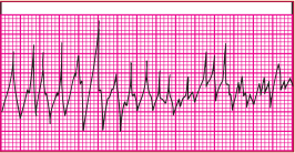
Artifact
Artifact, also called waveform interference, may be seen with excessive movement (somatic tremor). The baseline of the ECG appears wavy, bumpy, or tremulous. Dry electrodes may also cause this problem because of poor contact.
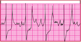
Interference
Electrical interference, also called 60-cycle interference, is caused by electrical power leakage. It may also occur because of interference from other room equipment or improperly grounded equipment. As a result, the lost current pulses at a rate of 60 cycles/sec. This interference appears on the ECG as a baseline that’s thick and unreadable.
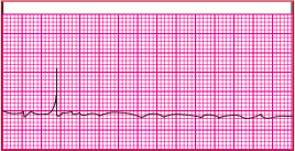
Wand ering Baseline
A wand ering baseline undulates, meaning that all waveforms are present but the baseline isn’t stationary. Movement of the chest wall during respiration, poor electrode placement, or poor electrode contact usually causes this problem.
Faulty equipment, such as broken leadwires and cables, can also cause monitoring problems. Excessively worn equipment can cause improper grounding, putting the patient at risk for accidental shock.
| That’s a wrap! |
Leads and Planes
Types of ECGs
12-Lead ECG
Leads I, II, and III
Precordial Leads
Modified Leads
Electrode Configurations
ECG Strip
Monitoring Problems
|
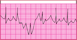
Be aware that some types of artifact resemble arrhythmias and the monitor will interpret them as such. For example, the monitor may sense a small movement, such as the patient brushing his or her teeth, as a potentially lethal ventricular tachycardia. So, remember to treat the patient, not the monitor. The more familiar you become with your unit’s monitoring system—and with your patient—the more quickly you can recognize and interpret problems and act appropriately.
