A. Sinus Node Dysfunction
Sinus node dysfunction (“sick sinus syndrome”) is usually due to age-dependent and progressive degenerative fibrosis of the sinus node and sinoatrial (SA) area (Table 14–1). Often, the degenerative process also involves the approaches to the AV node, the AV node itself, the His bundle, as well as the intraventricular conduction system; as many as 25–30% of patients with sinus node dysfunction have evidence of AV conduction disease.
Table 14–1. Causes of Sinus Node Dysfunction
Degenerative Ischemic (inferior wall MI, Bezold-Jarisch reflex) Inflammatory (pericarditis, collagen vascular diseases) Infiltrative (amyloidosis, sarcoidosis, hemochromatosis) Hypothyroidism Hypothermia Hypoxemia Medications β-Blockers Non-dihydropyridine calcium channel blockers (diltiazem, verapamil) Digoxin (with high prevailing vagal tone) Class I antiarrhythmic agents (flecainide, propafenone) Class III antiarrhythmic agents (amiodarone, sotalol) Other cellular ion channel blockers (ivabradine) Acetylcholinesterase inhibitors (donepezil) Sympatholytic drugs (clonidine, methyldopa) Lithium |
MI, myocardial infarction.
Respiratory sinus arrhythmia, in which the sinus rate increases with inspiration and decreases with expiration, is not an abnormal rhythm and is mostly seen in young healthy persons. Nonrespiratory sinus arrhythmia, in which phasic changes in sinus rate are not due to respiration, may be accentuated by the use of vagotonic agents, such as digoxin and morphine, and is more likely to be observed in older patients who have underlying cardiac disease, although the arrhythmia itself is not a marker for structural heart disease; its mechanism is unknown. Ventriculophasic sinus arrhythmia is an unusual rhythm that occurs during advanced second-degree or complete AV block; it is characterized by shorter P-P intervals that enclose QRS complexes. The mechanism is not known with certainty but is thought to be related to the effects of mechanical ventricular systole. The ventricular contraction increases blood flow to the sinus node, thereby transiently increasing its firing rate; an increase in intra-atrial pressure causes subsequent reduction in sinus rate. Ventriculophasic sinus arrhythmia is not a pathologic arrhythmia and should not be confused with premature atrial depolarizations or SA block. None of the sinus arrhythmias indicate sinus node dysfunction.
Chronotropic incompetence is the inability to increase the heart rate to match the oxygen demand from increased activity. Although the definition of chronotropic incompetence is not standardized and the underlying mechanism is still not fully understood, it is an important condition that is debilitating and has been reported to be an independent predictor of mortality. It appears to be related to dysfunction of autonomic regulation that can worsen with age and is frequently confounded by the effects of medications that cause sinus bradycardia (β-blockers, rate-limiting calcium channel–blocking agents diltiazem and verapamil, digoxin, and antiarrhythmic agents such as amiodarone and sotalol; Table 14–1 and Figure 14–2). If these medications are necessary treatments, permanent cardiac pacing is indicated.
Sinus node dysfunction can be present when sinus bradycardia, SA block, sinus pauses, sinus arrest, or a combination of these exist (Figures 14–1, 14–2, 14–3, 14–4, 14–5). Marked sinus bradycardia and prolonged sinus pauses, however, can be observed in clinically normal individuals without structural heart disease in the setting of increased vagal tone, such as during sleep. Hypoxemia from obstructive sleep apnea accentuates vagal tone, and both supplemental oxygen and continuous positive airway pressure can eliminate bradycardia and pauses. In some patients, coughing, swallowing, or vomiting can be identified as a trigger that causes sinus slowing or pause; in some cases, high acetylcholine levels may be responsible. Vagal stimulation, often from an identifiable trigger (Table 14–2), is commonly responsible for sinus bradyarrhythmias observed in patients in the intensive care setting. Vagally mediated sinus bradycardia or pauses should not prompt consideration for cardiac pacing, either temporary or permanent.
Figure 14-1. Ladder diagrams illustrating sinus bradycardia and sinoatrial block, types I and II. ECG, electrocardiogram; SA, sinoatrial; SAA, sinoatrial area; SN, sinoatrial node.
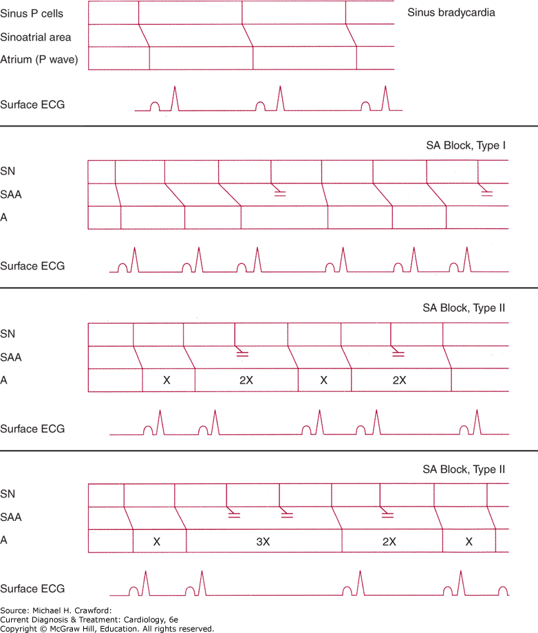
Figure 14-2. This 83-year-old woman was being treated for heart failure with reduced ejection fraction and was receiving 200 mg/day of amiodarone for episodes of nonsustained ventricular tachycardia. She complained of profound effort fatigue but no symptoms of heart failure. Electrocardiogram reveals an atrial bradycardia at a rate of about 38 bpm. The P waves vary in morphology, suggesting some wandering of the atrial pacemaker. Left axis deviation and a left intraventricular conduction delay with ST- and T-wave abnormalities are present. The atrial bradycardia was presumed to be due to the amiodarone, which was discontinued, resulting in appreciable increase in a stable sinus rhythm, with amelioration of the patient’s effort fatigue.
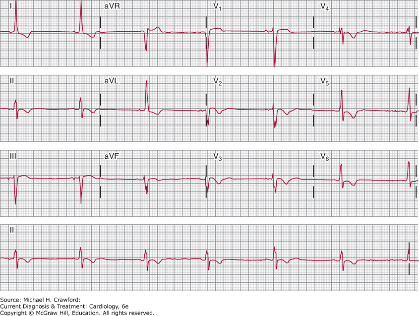
Figure 14-3. Continuous modified lead II ambulatory electrocardiographic recording in a patient with recurrent presyncopal spells. Sinus rhythm is present in the top strip; the second strip shows marked sinus slowing, followed by a 17-second period of sinus arrest without the appearance of a QRS escape rhythm. Sinus rhythm reappears in the fourth strip, gradually increasing its rate until stable rhythm is restored in the bottom strip. The absence of an escape rhythm raises the possibility of diffuse disease of the conduction system and impulse-generating tissue.
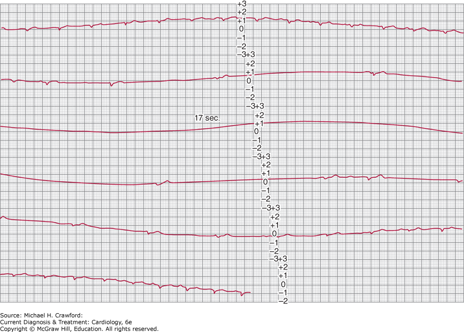
Figure 14-4. Progressive decrease in P-wave cycle lengths followed by a pause in P-wave rate, indicating type I second-degree sinoatrial block. The pauses in sinus rate are less than twice the preceding sinus cycle lengths, satisfying the criteria for Wenckebach periodicity. MCL, modified chest lead.
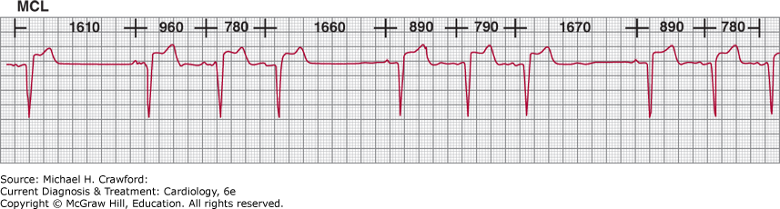
Figure 14-5. Irregular pauses in sinus rate, which occur abruptly and are not multiples of a basic sinus-cycle length. Best characterized as sinus pauses rather than sinoatrial block or sinus arrest, this rhythm indicates the existence of sinus node dysfunction. MCL1, modified chest lead.
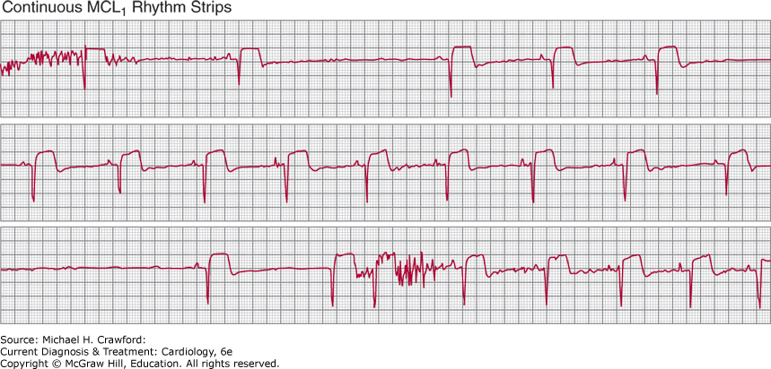
Table 14–2. Conditions Associated with Vagally Mediated Bradyarrhythmias
Sleep Highly conditioned state Isotonic exercise conditioning Coughing Swallowing Vomiting, retching Suctioning Nasal intubation Gastric intubation Urination Defecation Central nervous system trauma with high intracranial pressure |
SA block occurs when the impulse generated by the sinus node fails to exit the sinus node through SA tissue, resulting in an absent P wave on the surface electrocardiogram (ECG). In second-degree type I (or Wenckebach) exit block, the P-P intervals progressively shortens prior to the absent P wave; this phenomenon is observed because there is less incremental delay with each successive impulse transmission (see Figures 14–1 and 14–4). In second-degree type II exit block, abruptly longer P-P intervals are seen without progressive shortening, and the longer P-P interval is a multiple of the underlying sinus interval (see Figure 14–1). SA exit block of 2:1 or higher degree cannot be distinguished from sinus bradycardia on the surface ECG.
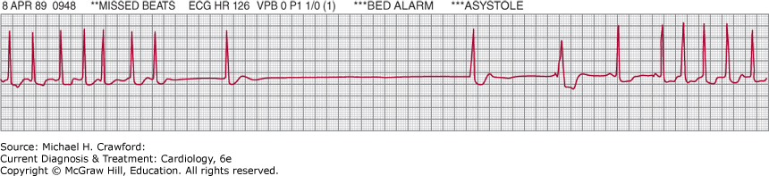
Bradycardia-tachycardia syndrome is characterized by episodes of both bradycardias and supraventricular tachyarrhythmias (Figure 14–6). The bradycardia is due to sinus node dysfunction (sinus arrest or SA exit block); the supraventricular tachyarrhythmias may be atrial tachycardia, atrial flutter, atrial fibrillation, AV reciprocating tachycardia, or AV nodal reentry tachycardia (see Chapter 11); more than one type of tachycardia may occur in the same patient. Bradycardia-tachycardia syndrome often represents diffuse conduction system disease but is not necessarily associated with structural heart disease.
Figure 14-6. Lead II rhythm strip characteristic of bradycardia-tachycardia syndrome, recorded from a patient with palpitations and intermittent dizzy spells.
The natural history of sinus node dysfunction is one of variable progression to an absence of identifiable sinus activity, with the process taking from 10 to 30 years. The condition itself is not associated with a high risk of arrhythmic death, although the morbidity caused by sudden onset bradycardia can be considerable. The ultimate prognosis for the patient with sinus node dysfunction typically depends on the presence and severity of underlying heart disease or the involvement of other portions of the conduction system through diffuse fibrosis, rather than on the sinus bradyarrhythmia itself.
B. Atrioventricular Block
Delay or block can occur anywhere along the course of the AV conducting system, which is made up of the AV node, His bundle, bundle branches, and fascicles. Like sinus node dysfunction, AV nodal-His block and bundle branch block (BBB) are often the result of sclerodegenerative processes; these processes can also involve the approaches to the AV node. Acquired AV nodal block is often due to acute ischemia and infarction (especially involving the inferior wall and right ventricle), infection, medications, and trauma (Table 14–3).
Table 14–3. Causes of Atrioventricular Block
Congenital Genetic (SCN5A mutations) Degenerative (Lenègre and Lev’s diseases) Ischemic (inferior wall MI, anterior wall MI, ischemic cardiomyopathy) Infectious (Lyme carditis, aortic valve endocarditis) Inflammatory (myocarditis, collagen vascular diseases) Infiltrative (amyloidosis, sarcoidosis, hemochromatosis, neoplasm) Neuromuscular (myotonic muscular dystrophy, Kearns-Sayre syndrome, Erb dystrophy, peroneal muscular atrophy) Calcific (aortic and mitral valve disease) Iatrogenic Medication (β-blockers, diltiazem, verapamil, digoxin, antiarrhythmic drugs, donepezil) Valvular intervention (aortic valve surgery, TAVR) Catheter ablation (AV nodal ablation) Alcohol septal ablation
|
AV, atrioventricular; MI, myocardial infarction; TAVR, transcatheter aortic valve replacement.
The AV node (or junction) is made up of three regions: atrionodal, central compact, and nodal-His. Cells of the atrionodal region have a relatively fast depolarization rate (45–60 bpm) and are responsive to autonomic nervous system input, whereas cells of the nodal-His region have a slower depolarization rate (about 40 bpm) and are generally unresponsive to autonomic influences. The site of origin of a junctional rhythm will therefore determine its rate, responsiveness to vagal and adrenergic input, and consequently the presence and severity of clinical symptoms.
The natural history of patients with AV block depends on the prognosis of any underlying condition and on the site of AV block. When the site of block is at the level of the AV node, there is a reliable escape rhythm that originates from AV node distal to the block; when the block is below the AV node, resulting ventricular escape rhythms can be slow and inconsistent and bradyasystolic arrests can ensue. First-degree AV block typically has little prognostic import. Marked PR prolongation, however, can physiologically resemble retrograde ventriculoatrial conduction with loss of optimal AV synchrony, thus causing debilitating symptoms. Persistent second-degree (type I, type II, 2:1, and advanced) and third-degree (or complete) AV block become increasingly symptomatic with higher degrees of block. Regardless of severity of block or symptoms, AV block below the level of the AV node can be associated with adverse outcomes including cardiac arrest and death.
A. Symptoms & Signs
The symptoms resulting from conduction disorders reflect cerebral hypoperfusion, low cardiac output at rest or during exercise, and rarely, hemodynamic collapse. Symptoms, which are often subtle, can be episodic or chronic and can change over time. Because a patient often adapts activity levels to compensate for the impairment in heart rate response, significant symptoms may not be evident unless the patient is closely questioned about specific activities and effort tolerance, or the clinician actually observes the patient during performance of activities of daily living such as walking or during formal treadmill exercise tests.
Syncope is the classic symptom of cerebral hypoperfusion due to bradycardia; however, symptoms of presyncope such as dizziness, lightheadedness, and confusion can reflect the same pathophysiology and warrant the same aggressive approach to diagnosis and management. It should be emphasized that patients with cerebral hypoperfusion often have impairment of memory surrounding the syncopal or presyncopal episodes and may therefore be unable to provide an adequate or accurate history surrounding the events; witnesses, if present, can contribute significant information in these cases.
Patients with sinus node dysfunction, or AV block with an escape rhythm unresponsive to autonomic nervous system input, cannot increase their heart rate in response to increases in oxygen demand. These patients are, therefore, intolerant of effort and report symptoms of exercise-related breathlessness, weakness, and fatigue. These symptoms, which can be disabling, are often confused with other conditions such as hypothyroidism, medications, underlying heart disease, deconditioning, or simply older age.
During periods of AV block, the atria and ventricles often depolarize and contract asynchronously or with dyssynchronous timing. There are variable increases in atrial pressure and volume depending on the degree of AV valve opening at the onset of ventricular systole. The resulting atrial stretch and secretion of atrial natriuretic peptide produce reflex systemic hypotension and cerebral hypoperfusion. In addition, the increases in left atrial and pulmonary venous pressures can cause shortness of breath and pulmonary venous congestion, including frank pulmonary edema. Misdiagnosis of refractory left ventricular dysfunction is not infrequently made in this situation.
Patients who have bradycardia-tachycardia syndrome (Figure 14–6) have symptoms attributable to both bradycardia and tachycardia. During tachyarrhythmias, the patient can experience uncomfortable palpitations, breathlessness, chest discomfort, and, at times, symptoms of cerebral hypoperfusion from excessively rapid heart rates.
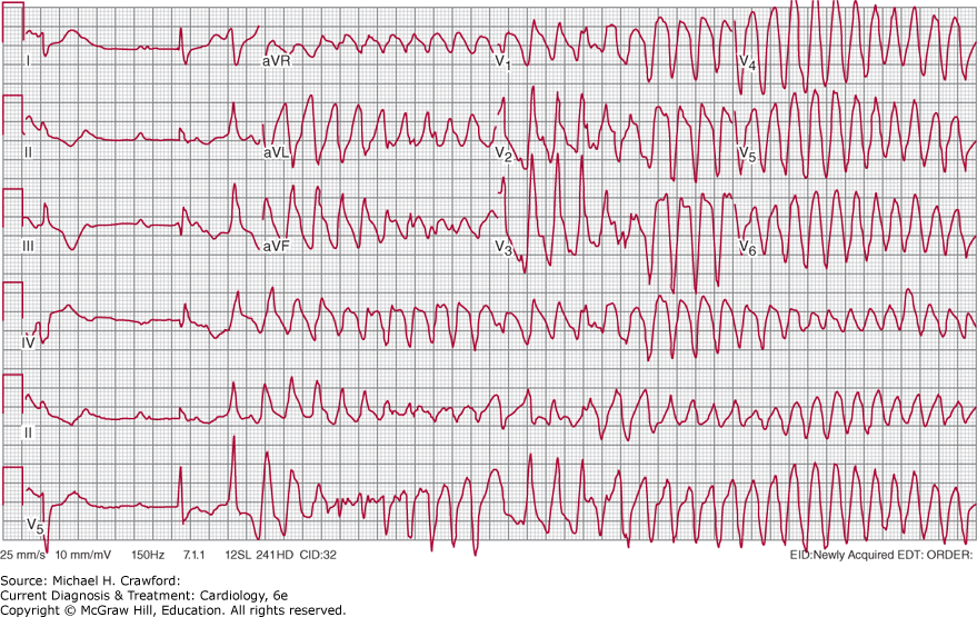
Distinct from bradycardia-tachycardia syndrome, bradycardias can, on occasion, lead to a potentially lethal form of polymorphic ventricular tachycardia known as bradycardia- or pause-dependent ventricular tachycardia (Figure 14–7). This is a manifestation of torsade de pointes as it occurs in the setting of QT interval prolongation brought on by the longer R-R intervals associated with either bradycardia or pauses. Symptoms in these patients can include not only palpitations, presyncope, and syncope, but also cardiac arrest.
Figure 14-7. Pause-dependent ventricular tachycardia. The initial seconds recorded on the 12-lead electrocardiogram and three-lead rhythm strips reveal complete heart block. The heart block results in a long RR cycle length and prolongation of the following QT interval. The QT prolongation results in polymorphic ventricular tachycardia (torsade de pointes).
B. Physical Examination
The physical examination of the patient with bradycardia reflects the origin of the QRS rhythm and the AV relationship more than the heart rate per se. Junctional or ventricular escape rhythms resulting from atrial bradycardia or AV block produce AV dyssynchrony. This dyssynchrony results in varying degrees of atrial contribution to ventricular filling, as well as varying stroke outputs and systolic blood pressures. Because AV dyssynchrony causes changes in the positions of the mitral and tricuspid valves relative to their fully closed or open positions, the intensity of the first heart sound will vary, as will the audibility of atrial gallop (S4) sounds and the intensity of semilunar valve systolic ejection murmurs and AV valve regurgitant murmurs.
Examination of the venous pulse contour in the neck can reveal cannon a waves (due to atrial systole occurring against closed AV valves) and prominent cv waves (due to ventricular contraction occurring with the AV valves partially or even completely open), and the diagnosis of AV block can be made by recognizing these findings. Central venous pressure elevation is a common physical finding that is independent of the venous pulse contour.
The carotid pulse may vary in volume and upstroke velocity in patients with AV dyssynchrony. Auscultation of the chest may disclose crackles, which reflect increased pulmonary venous pressure and valvular regurgitation rather than systolic or diastolic ventricular dysfunction. The liver may be enlarged and pulsatile because of transmitted a and cv waves. Peripheral edema may also be present if AV dyssynchrony is chronic.
These same physical findings can also occur in patients who have sinus rhythm but develop AV dyssynchrony from being paced by a single-chamber ventricular pacing system. In these patients, symptoms of weakness, fatigue, and congestive heart failure, together with physical findings indicating AV dyssynchrony, constitute “pacemaker syndrome.” This syndrome is treated by upgrading the single-chamber ventricular pacing system to a dual-chamber system in which sensing of the atrial rhythm triggers a paced ventricular response that restores AV synchrony (see later section, Permanent Pacing).
In addition to the findings described earlier, significant bradycardia (<40 bpm) may result in ventricular dilation, and the Frank-Starling effect results in an increase in stroke volume and cardiac output despite the slow heart rate. This dilation may lead to left ventricular gallop sounds and regurgitant murmurs, which can disappear when normal heart rate is restored. The enlarged ventricles may be palpable.
C. Diagnostic Studies
1. Sinus Node Dysfunction
A. Electrocardiography
The P waves inscribed on the surface ECG represent atrial depolarizations. Sinus node depolarization precedes atrial depolarization and is not seen on the surface ECG. The P waves that result from sinus-generated impulses must be inferred from their morphology and frontal plane axis.
The sinus P wave has a mean frontal plane axis of +15뀀 to +75뀀 and is upright in leads I, II, and aVF, inverted in lead aVR, and variable in leads III and aVL. In the horizontal plane, the sinus P wave can be inverted in lead V1 but is upright in leads V3–V6. Respiratory variation in the sinus P-wave contour can be seen in the inferior leads and should not be confused with wandering atrial pacemaker, which is unrelated to breathing. Sinus arrhythmia is present when the P-wave morphology is normal and consistent, and the P-P intervals vary by more than 160 ms. SA block exists when some impulses generated by the sinus pacemaker cells do not exit the SA node to depolarize the atria; in the absence of atrial depolarization, a P wave will not be inscribed on the surface ECG. “Advanced” SA block, in which most of the sinus impulses fail to exit the SA node to the atrium, is inscribed on the surface ECG as pauses in sinus rhythm. These pauses often cannot be differentiated from sinus arrest caused by failure of impulse generation by the sinus node. If the pauses between sinus P waves are multiples of a basic P-wave rate, however, the diagnosis of type II second-degree or “advanced” SA block can be made.
B. Electrophysiologic Studies
Sinus node function can be evaluated in the electrophysiology laboratory by means of simultaneous surface and intracardiac electrographic recordings made during basal conditions, physiologic and pharmacologic interventions, and atrial pacing. This evaluation can be undertaken in patients with either symptomatic sinus bradycardia or bradycardia-tachycardia syndrome. It can also be used in patients with recurrent syncope of unclear etiology, although the diagnostic yield and predictive value for syncope is limited. Measurements include the intrinsic heart rate, the sinus node recovery time (SNRT), and the response to parasympathetic (vagal) stimulation as assessed by carotid sinus massage.
The intrinsic heart rate (ie, the rate independent of autonomic influences) is the sinus rate during pharmacologic denervation of the sinus node using a β-blocker and atropine. The intrinsic heart rate is sometimes used to distinguish healthy persons from those with sinus node dysfunction.
SNRT is the interval after sinus node suppression from overdrive atrial pacing to the first return of sinus node activity, manifested on the surface ECG by the postpacing sinus P-wave interval. The measured SNRT depends on several factors, among them the proximity of the pacing catheter to the sinus node, the presence or absence of SA entrance block (in which atrial impulses fail to enter and depolarize the sinus node), and local neurohormonal influences. In normal persons, atrial pacing at rates of 120–130 bpm for 30 seconds or more is followed by a return of sinus node activity at a reproducible interval, with the basic sinus rate generally recovered within three postpacing beats. The usual SNRT is less than 1.5 seconds, although considerable variation may exist depending on the prevailing autonomic tone. A corrected SNRT can be calculated by subtracting the basic sinus rate from the SNRT; a normal value is usually between 350 and 550 ms. In patients with sinus node dysfunction, SNRT may not be reproducible and tend to be longer after more prolonged periods of pacing; return to the basic sinus rate within three postpacing beats is also inconstant and may be followed by additional (secondary) pauses in rate.
Electrophysiologic testing of sinus node function is neither specific nor sensitive; abnormal results can be seen in patients without sinus bradycardia and normal results in those with symptomatic sinus node disease. The diagnosis of sinus node dysfunction remains primarily a clinical one.
C. Ambulatory ECG Monitoring
Establishing correlation between symptoms and documented bradycardia is necessary for the diagnosis of sinus node dysfunction, and essential when deciding if permanent pacing is indicated. Advances in ambulatory ECG monitoring have resulted in a wide range of modalities that allow for longer monitoring durations, and that are more accessible and convenient for patients.
Continuous ECG monitors have the advantage of uninterrupted recording over a period of time, but technology constraints have until recently limited the monitoring duration to 24–48 hours (eg, Holter monitors); the need for multiple electrodes and wires has also been a limitation that required application of the monitor by medical personnel and can be a cause of inconvenience for patients. Various patch monitors without wires have been designed that can be self-applied by the patient and can record continuously up to 2 weeks. If continuous monitoring is needed beyond 2 weeks, an implantable cardiac monitor with a battery longevity up to 4.5 years that is inserted subcutaneously overlying the chest wall can be considered.
Event monitors are able to be worn or carried for longer periods of time but have the limitation of recording only specific sequences. Wearable event monitors that utilize electrodes and wires can be worn up to 30 days. Portable ECG recorders have the advantage of longer observation durations but recording starts after the onset of symptoms and the patient must have the recorder on-hand. Personal portable ECG monitors have the advantage of being either wearable, as in the form of a smartwatch, or ultraportable, as being able to fit in a wallet, and are reliably available to record with the onset of symptoms; the ECG tracings from these portable monitors are increasingly being accepted by clinicians as achieving diagnostic quality.
D. Exercise Testing
Treadmill exercise testing can be of substantial value in assessing chronotropic response (“chronotropic competence”) to increases in metabolic needs in patients with sinus bradycardia in whom sinus node dysfunction is suspected. The definition of chronotropic incompetence is not agreed on, but it is reasonable to designate it as consisting of either an inability to achieve a heart rate exceeding 75% of age-predicted maximum (usually taken as 220 − age), or 100–120 bpm at maximum effort. Irregular (and nonreproducible) increases, and even decreases, in sinus rate during exercise can occur but are rare. Abrupt rate changes during the postexercise recovery period can also occur but are rare. Chronotropic incompetence can result from medications (Table 14–1) and should be distinguished from intrinsic sinus node dysfunction.
The Bruce treadmill exercise protocol, which is usually used to diagnose the presence and severity of coronary artery disease, is generally inappropriate for patients with sinus node dysfunction in whom the goal is to assess heart rate at lower workloads expected to be encountered during average daily activities. Specific protocols have been developed for this purpose. In addition to documenting chronotropic incompetence, treadmill exercise testing can be used to aid in optimal programming of rate-adaptive cardiac pacemakers that are usually required in these patients.
2. Atrioventricular Block
A. Electrography and Electrocardiography
His bundle electrography has provided important information regarding normal and abnormal AV conduction in humans. The technique involves positioning a multipolar electrode catheter across the tricuspid valve in proximity to the AV nodal-His bundle area to record electrical activity as it traverses these structures. Because of its location, the catheter records electrical activity at the level of the low right atrium, His bundle, proximal right bundle branch, and right ventricular septum. The sinus node pacemaker cells normally initiate the cardiac impulse, but they are not registered on the surface ECG; the onset of the P wave on the surface ECG signifies the beginning of atrial depolarization. Because the intracardiac electrode catheter lies at the level of the low right atrium, early atrial depolarization will not be detected by the catheter; as the atrial depolarization wavefront reaches the low right atrium, a deflection is registered (A). As the impulse traverses and depolarizes the His bundle, another deflection is registered (H). His bundle deflection is then followed by a ventricular deflection (V), which is registered at the time the wavefront of ventricular depolarization reaches the electrodes; ventricular deflection recorded by the catheter often occurs after the onset of QRS complex on the surface ECG.
His bundle electrography is useful in indicating the site of AV conduction delay or block. Normally, the conduction time through the AV node is 90–150 ms, and the conduction time through the His-Purkinje system is 35–55 ms. In a patient with a prolonged PR interval, a prolonged AH interval signifies delayed impulse conduction within the AV node, and a prolonged HV time represents delayed impulse conduction within the His bundle or the bundle branches. Conduction delay within the His bundle itself manifests as more than one His deflection (“split” His deflections).
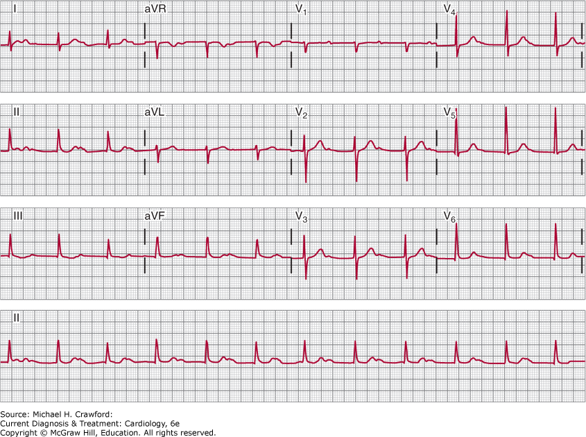
In first-degree AV block (a delay in conduction between the atria and the ventricles), all atrial impulses are conducted to the ventricles; it is characterized by a prolonged PR interval that exceeds 200 ms (Figure 14–8). The components of a normal PR interval are interatrial conduction (10–50 ms), AV nodal conduction (90–150 ms), and intra-His and His-Purkinje conduction (35–55 ms). Conduction delay in first-degree AV block can thus represent prolonged intra-atrial, AV nodal, intra-His, or His-Purkinje conduction, and the His bundle electrographic recordings help clarify the location of the delay.
Figure 14-8. Sinus rhythm with marked first-degree atrioventricular (AV) block. All P waves are conducted to the ventricles. The PR intervals are about 480 ms. The RP intervals are shorter than the PR intervals, which, in some patients, can cause symptoms due to suboptimally timed AV depolarization-contraction sequences. Despite the length of the PR intervals, this conduction disturbance is generally benign; evolution to second-degree AV block can take years.
In patients with a QRS complex that is narrow and normal-appearing, first-degree AV block is AV nodal in more than 85% and is intra-His in less than 15%. In patients with a wide QRS complex due to BBB or nonspecific intraventricular conduction delay, first-degree AV block is AV nodal in less than 25%, infranodal in about 45%, and at more than one site in about 33%.
In second-degree AV block, not all atrial impulses are conducted to the ventricles. The ratio of P waves to QRS complexes is referred to as the AV conduction ratio. Type I (Wenckebach) second-degree AV block is present when the conduction of atrial impulses to the ventricles is progressively delayed because of AV (generally AV nodal) refractoriness, with eventual failure of conduction of an atrial impulse to the ventricles. The AV conduction ratio in type I second-degree AV block can be 3:2, 4:3, 5:4, and so on; this ratio is also referred to as a Wenckebach period. AV conduction ratios in type I second-degree AV block need not be constant, and therefore, the Wenckebach period may not be reproducible. Because type I second-degree AV block usually occurs within the AV node, the PR interval of the first conducted P wave of the Wenckebach period is often prolonged, and because this conduction disturbance does not involve the bundle branches, the QRS complexes are expected to be narrow and normal-appearing unless there is preexisting bundle branch disease.
In a typical, or classic, Wenckebach period, the PR intervals progressively lengthen, the R-R intervals progressively shorten, and the R-R interval encompassing the nonconducted P wave is less than twice the preceding R-R interval. Typical Wenckebach periods are usually seen with low AV conduction ratios (3:2, 4:3, and 5:4), but as the AV conduction ratio increases (exceeding 6:5), more and more Wenckebach sequences are atypical. If the sinus rate is not constant, for example in vagally mediated bradyarrhythmias, sequences that resemble Wenckebach conduction often occur; they should not, however, be considered type I second-degree AV block, in which the sinus rate needs to be constant for the diagnosis to be made.
In type II second-degree AV block, atrial impulses intermittently fail to be transmitted to the ventricles, but progressive conduction delay prior to the AV conduction failure does not occur. Because prior conduction delay from the atria is not present, the failure of antegrade conduction is often abrupt and unpredictable (paroxysmal) and may be advanced. In contrast to type I second-degree AV block, in which the conduction delay is usually in the AV node, the conduction delay in type II second-degree AV block can be within the His bundle or, more commonly, distal to the His bundle in the bundle branches. If the block is within the His bundle, the QRS complexes will be narrow and normal-appearing, or only mildly aberrant, unless preexisting BBB is present. If the block is infra-His, the QRS complexes will show a BBB pattern. In contrast to type I second-degree AV block, the PR interval of the conducted P waves is constant and often (but not always) normal (Figure 14–9).
Figure 14-9. A: This electrocardiogram was recorded in a patient with presyncopal spells who was about to undergo exercise treadmill testing. The atrial rhythm is sinus at a rate of about 68 bpm. The PR intervals of the conducted QRS complexes are all about 240 ms. The QRS complexes are narrow, and nondiagnostic ST- and T-wave abnormalities are present. A 2:1 atrioventricular (AV) conduction develops abruptly during the recording. The prolonged PR intervals of the conducted P waves, as well as the narrow morphology of the QRS complexes (indicating absence of bundle branch system disease), could suggest that the 2:1 AV conduction represents AV nodal block; intra-His block, however, is suggested by the absence of prolongation of the PR intervals prior to the nonconducted P waves. Changing of the AV conduction ratio from 2:1 to 3:2, 5:4, and so on, would help establish the presence of AV nodal block. This could be achieved by atropine or exercise testing, during which adrenergic drive would be expected to facilitate AV conduction. B: The patient achieved stage IV of the Bruce protocol during treadmill testing. The atrial rate was 150 bpm. At peak effort and for the first 2 minutes of the postexercise recovery period, 3:1 AV block developed abruptly and was associated with the patient’s typical presyncopal symptoms. AV block developing during exercise, although rare, is always abnormal and, if the QRS complexes are narrow or normal appearing, indicates intra-His block. Permanent cardiac pacing is required.
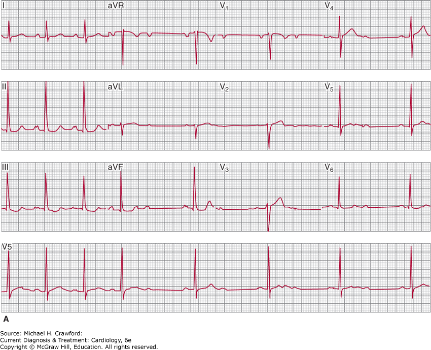
Figure 14-9.
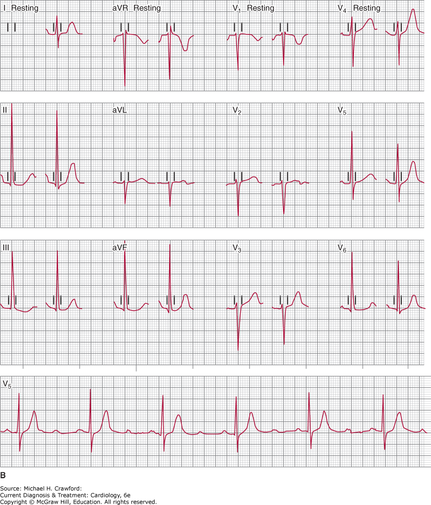
Second-degree AV block with 2:1 AV conduction ratio may represent either AV nodal or His-Purkinje block (Figures 14–10 and 14–11). Two consecutive PR intervals are not recorded in 2:1 AV conduction; therefore, the presence or absence of progressive PR prolongation cannot be ascertained and distinguishing the site of block may be difficult. If the PR interval of the conducted P waves is prolonged and the QRS complexes are narrow and normal-appearing, AV nodal block is probably present. If the PR interval of the conducted P waves is normal and the QRS complexes have a BBB pattern, His-Purkinje block is probably present. If the PR interval of the conducted P wave is prolonged and the QRS complexes have a BBB pattern, or if the PR interval of the conducted P wave is normal and the QRS complexes appear normal, it may not be possible to distinguish between the two types, and more than one site of AV block may also be present.
Figure 14-10. The atrial rhythm is sinus, and 2:1 atrioventricular (AV) conduction is present. The PR intervals of the conducted beats are normal at about 190 ms. The QRS complexes are narrow and normal appearing. The 2:1 AV conduction could represent either AV nodal or His-Purkinje block. When AV nodal block is present, the PR intervals of the conducted complexes are often prolonged and the QRS complexes narrow and normal appearing, whereas in infra-Hisian block, the PR intervals of the conducted complexes are generally normal and the QRS complexes broad, indicating bundle branch disease. In this tracing, the PR intervals are normal. The site of block cannot be known with certainty from this tracing, and manipulation of the AV conduction ratio by atropine or exercise, which facilitates AV conduction, might be required. AV nodal block generally does not require cardiac pacing. If the block is within the His bundle, both the PR interval and QRS complex width are typically normal (electrophysiologic study may be needed to distinguish from AV nodal block), and permanent cardiac pacing is indicated.
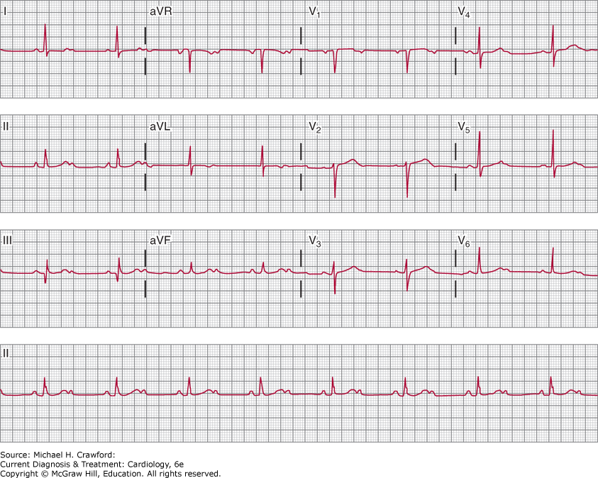
Figure 14-11. Second-degree atrioventricular (AV) block, with 2:1 conduction ratio and evidence of bundle branch disease. The prolonged PR interval of the conducted P waves and the left bundle branch block pattern of the conducted QRS complexes make localization of the site of block difficult; the prolonged PR interval suggests AV nodal disease, whereas the wide QRS complexes support infra-Hisian disease; electrophysiologic study may be necessary to document the site of conduction delay and to decide whether permanent cardiac pacing is required.
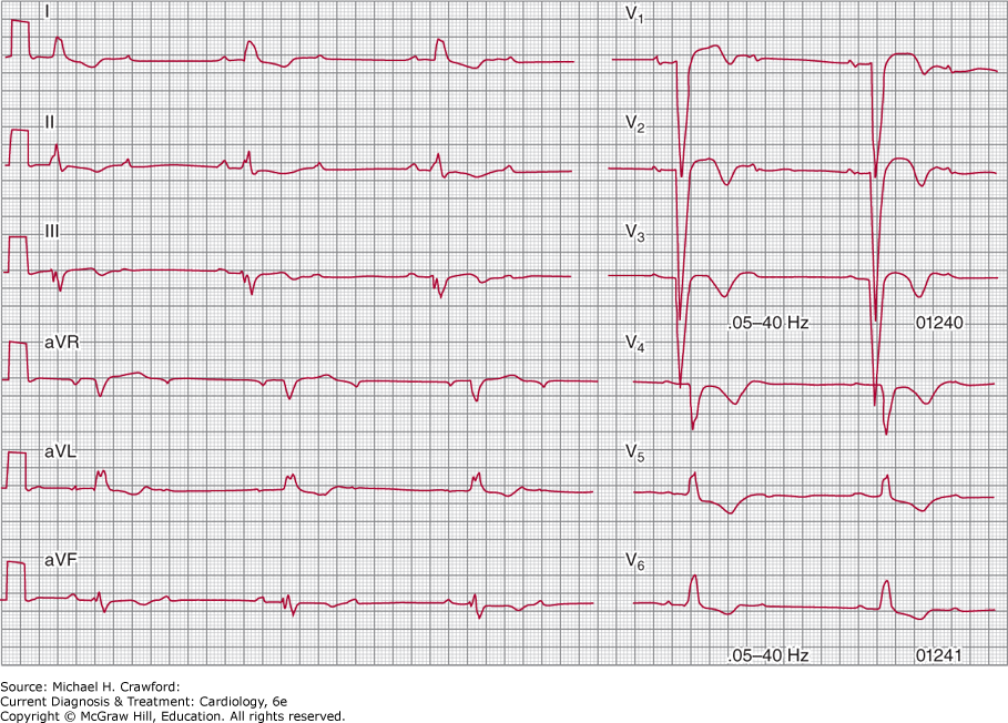
Altering the AV conduction ratio by means of carotid sinus massage or intravenous atropine will often allow identification of the nature of the AV block and thus its location (Figure 14–9). If the site of block is in the AV node, the AV conduction ratio will increase due to the vagotonic effect of carotid sinus massage (eg, from 2:1 to 3:1 or 4:1) and improving with the vagolytic effect of intravenous atropine (eg, from 2:1 to 3:2 or 4:3). Conversely, His-Purkinje block is heart rate dependent, and AV conduction ratio improves (eg, from 2:1 to 3:2 or 4:3) due to the slower sinus rate caused by carotid sinus massage; with faster sinus rate due to the intravenous atropine, the AV conduction ratio will increase (eg, from 2:1 to 3:1 or 4:1).
In advanced second-degree AV block, the AV conduction ratio is 3:1 or greater, and atrial impulses are not consistently conducted to the ventricles. In contrast, in third-degree (“complete”) AV block, no atrial impulses are conducted to the ventricles despite temporal opportunity for this to occur, and the atria and ventricles are depolarized by their respective pacemakers, which are independent of each other (Figure 14–12). The atrial rate in complete AV block is almost always faster than the ventricular rate. The QRS rhythm, or the escape rhythm, originates distal to the site of block and may be in the AV junction, His bundle, bundle branches, or distal Purkinje system. The morphology of the QRS complexes and their rate will depend on their site of origin. A narrow QRS complex escape rhythm originates from the AV junction. On the other hand, a wide QRS complex rhythm is not a reliable guide to the origin of the rhythm because rhythms originating in the longitudinally separated predivisional region of the His bundle can have a wide QRS complex.
Figure 14-12. Complete atrioventricular (AV) block. The atrial and ventricular rhythms are independent of each other. The narrow, normal-appearing QRS complexes establish that the AV block is within the AV node or the His bundle.
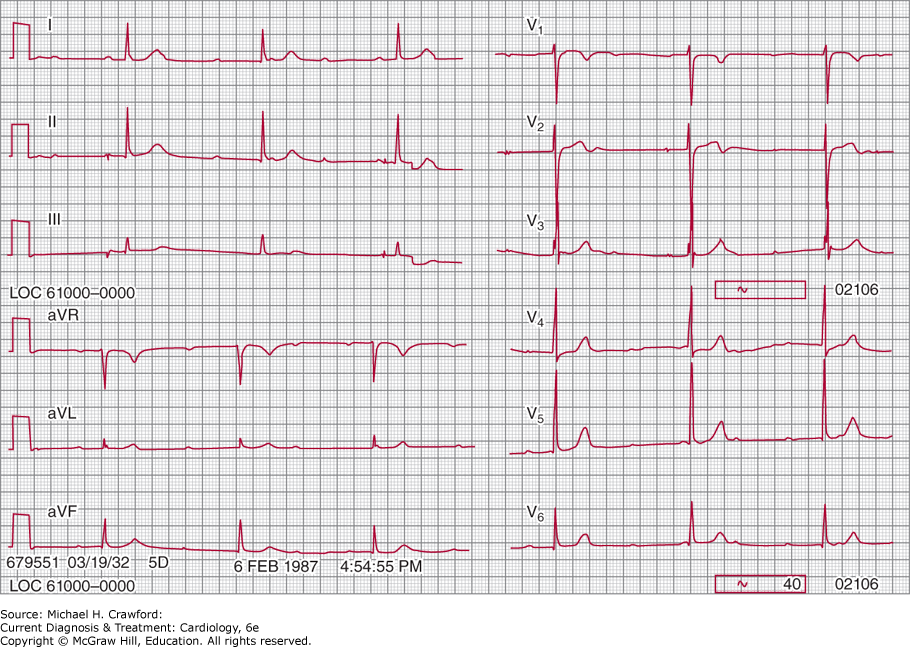
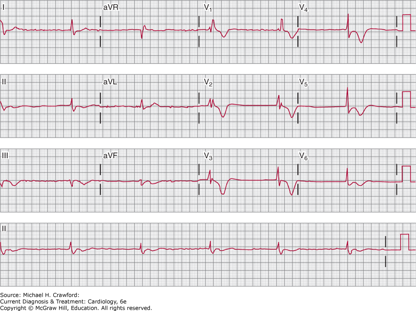
If the atrial rate is not sinus (eg, atrial fibrillation), the existence of advanced or complete AV block is diagnosed by the presence of a slow ventricular rate with varying intervals between the QRS complexes or by a slow and regular QRS rate (Figure 14–13), respectively. Atrial fibrillation and flutter are not uncommonly associated with advanced AV block and slow QRS rates. The rate of the ventricular rhythm, as well as the QRS-complex morphology, will depend on the site of origin of the rhythm. A regular rhythm in a patient with atrial fibrillation confirms the presence of complete AV block, with a QRS pacemaker originating below the level of conduction block that is independent of the atrial rhythm.
Figure 14-13. The atrial rhythm is fibrillation. The QRS rhythm is regular at a rate of about 33 bpm and displays a right bundle branch block pattern. The regularity of the rhythm indicates complete atrioventricular (AV) block, and the rate and morphology suggest a ventricular focus of origin. This rhythm could be due to digoxin toxicity or to the effects of calcium channel blockers or -blockers; if offending medications cannot be discontinued, permanent cardiac pacing is indicated. This rhythm and rate can also be seen in the absence of medications and after radiofrequency ablation of the AV node to treat uncontrolled ventricular rate in patients with atrial fibrillation; permanent cardiac pacing is required.
In vagally mediated block, a high degree of vagal tone, such as occurs with sympathetic withdrawal during sleep or in highly conditioned athletes, may be associated with slowing of the sinus rate, pauses in sinus rhythm, variable degrees of delay in AV conduction manifested by prolongation of PR intervals (often irregular), and failure of conduction of P waves resembling type I or II second-degree AV block (Table 14–4). It is important to recognize vagally mediated block because it often occurs in normal individuals as well as in patients with inferior or right ventricular myocardial infarction, or any other clinical condition in which hypervagotonia is present (Table 14–2). It not uncommonly accompanies the use of certain medications, notably β-blocking agents, some antihypertensive drugs, and occasionally, digoxin. It can also be seen during coughing (tussive bradycardia), swallowing (deglutition bradycardia), and yawning. In the critical care setting, vagally mediated block (and significant bradycardia) can occur during endotracheal suctioning or esophagogastric intubation and in patients with elevated intracranial pressure.
Table 14–4. Diagnostic Clues to Vagally Mediated Atrioventricular Block
Concomitant slowing of sinus rate Changing PR intervals, often with irregularity of sinus rates Atypical Wenckebach periods, often with inconstant PP intervals Inconstant escape rates Inconstant escape foci Transient nature of episodes Lack of reproducibility of episodes, duration Reversed or abolished by intravenous atropine or an increase in sympathetic tone |
B. Ambulatory ECG Monitoring
In the diagnostic evaluation of AV block, ambulatory ECG monitoring takes on a different role from that in sinus node dysfunction. Because there is the potential for cardiac arrest with infra-nodal AV block, electrophysiologic studies will usually be considered to establish the location of the AV block prior to prolonged ECG monitoring. The transient nature of AV block, especially early in the course of disease, makes event monitoring less useful unless the monitor is capable of looping memory that retains data for a few minutes before it gets overwritten; this allows for capture of ECG tracings several minutes prior to onset of symptoms and activation of the event monitor. The intermittent nature of AV block, with sometimes months between symptoms, requires that monitoring be of prolonged duration. Implantable cardiac monitors can be useful if the diagnosis of AV block or the decision for permanent pacing therapy is not clear after electrophysiologic studies.
C. Exercise Testing
Unlike the value of exercise testing in sinus node dysfunction for both diagnosis and evaluation of chronotropic competence, exercise testing in patients with AV block is generally less useful. AV node conduction is enhanced by the vagolysis and increased sympathetic drive that occurs with exercise. Thus, patients with first-degree AV block and type I second-degree AV block are expected to have shorter PR intervals during exercise; in patients with type I second-degree AV block, a longer Wenckebach period can develop (eg, 3:2 at rest becoming 6:5 during exercise). Patients with 2:1 AV conduction, in whom the site of conduction block may be uncertain, can benefit from exercise testing by observing whether the AV conduction ratio increases in a Wenckebach-like manner (eg, to 3:2 or 4:3) or decreases (eg, to 3:1 or 4:1) (Figure 14–9). In the latter case, the increase in the sinus rate finds the His-Purkinje system refractory, causing the higher degrees of block. This response, when observed, is always abnormal because it indicates intra- or infra-His block, which will require permanent cardiac pacing.
The major reversible causes of conduction system disturbances are high vagal tone and medications. High vagal tone, whether or not it is accompanied by withdrawal of sympathetic tone, can cause or contribute to both atrial and ventricular bradycardia. Vagally mediated bradycardias are usually transient and not accompanied by symptoms of presyncope or frank syncope, and no treatment is needed. Even when pauses are prolonged and symptomatic, permanent cardiac pacing is usually not indicated. If necessary, intravenous atropine can be used to facilitate AV nodal conduction to avoid ventricular bradycardia; however, the atropine-induced increase in atrial rate can lead to a paradoxical slowing of ventricular rate as a result of more rapid stimulation of, and encroachment on, the refractory period of the AV conduction system. Moreover, the effects of intravenous atropine are short-lived, and its long-term use is accompanied by significant side effects.
In contrast to the majority of vagally mediated bradycardias, “vasovagal” or vagally mediated syncope (hypotension with variable degrees of bradycardia or asystole) can be frequent, abrupt, unpredictable, and disabling. These highly symptomatic episodes, also referred to as “neurocardiogenic” or “neutrally mediated” syncopal syndromes, are generally not life-threatening but can have significant morbidity including serious injury. Predisposing factors such as volume depletion and prolonged standing should be avoided. Isometric contraction, such as by crossing legs, tensing the lower body, and vigorous handgripping, has been found to abort episodes, and patients should be instructed in these maneuvers.
Because left ventricular baroreceptor stimulation (from vigorous systolic ventricular contraction) and its consequent reflex peripheral vasodilation play a role in this syndrome, drugs having negative inotropic effects (eg, β-blockers) were postulated as potential medical therapies. Multiple studies have now shown β-blockers to be generally ineffective; there may be benefit among patients 42 years of age or older. α-Agonists, such as midodrine, have been used successfully with orthostatic hypotension, and to a lesser degree with vasovagal syncope. Fludrocortisone and selective serotonin reuptake inhibitors have been found to have variable degrees of effectiveness. The tendency for events to occur in clusters, sometimes separated by long periods of time, make daily use of medications typically unwarranted. In “malignant” vasovagal syncope (frequent attacks, severe events resulting in serious injury, prolonged asystole), permanent dual-chamber cardiac pacing can be considered, even though benefit of pacing has not been consistently shown. There is evidence that dual-chamber pacing reduces syncope in patients 40 years of age or older with spontaneous pauses ≥ 3 seconds documented with syncope or asymptomatic pauses ≥ 6 seconds. Special pacing algorithms can be used that detect abrupt falls in heart rate and respond with rapid pacing until the spontaneous heart rate increases.
Commonly used medications that cause or contribute to bradycardia do so by enhancing vagal tone (eg, digoxin), reducing the facilitation of AV conduction that results from sympathetic tone (eg, β-blockers and antiarrhythmic agents with β-blocking properties such as sotalol and propafenone), or acting directly on SA and AV conduction tissue (eg, verapamil and diltiazem). Simple withdrawal of these medications can reverse the bradycardia, although the process may require several days. If the offending medications are necessary to treat other conditions such as angina pectoris or heart failure and cannot be discontinued, permanent cardiac pacing will be required (Table 14–5).
Table 14–5. Common Indications for Permanent Cardiac Pacing
Sinus node dysfunction Atrioventricular block Acute myocardial infarction With persistent second-degree type II, advanced second-degree or third-degree AV block With transient advanced second- or third-degree AV block, and bundle branch block
Second-degree Type I, with symptoms Type II
Third-degree (complete) and advanced second-degree With symptoms (including symptoms resulting from necessary medications) With asystole ≥3 seconds, escape rate <40 bpm, or escape rhythm below the AV node, in awake patients With AF and ventricular pauses ≥5 seconds, in awake patients (including when resulting from necessary medications) After AV node ablation
Bundle Branch Block With syncope, HV interval ≥ 70 ms or infranodal block during EPS With alternating bundle branch block
Carotid sinus hypersensitivity Neurocardiogenic syncope |
AV, atrioventricular; EPS, electrophysiology study; HV, His ventricular.
Based on ACC/AHA/HRS 2008 guidelines for device-based therapy of cardiac rhythm abnormalities by Epstein AE, et al. Circulation. 2008;117:e350–e408, and 2018 ACC/AHA/HRS guideline on the evaluation and management of patients with bradycardia and cardiac conduction delay by Kusumoto FM, et al. Circulation, 2019;140: e282–e482.
It is important to exclude AV nodal blocking medications, such as digoxin, β-blockers, and rate-limiting calcium channel blockers, as a cause of, or contributor to, slow ventricular rates in atrial fibrillation and flutter; withdrawal of these drugs or reduction in dosage can result in reversal of the AV block, and permanent cardiac pacing can be avoided. If the ventricular rhythm is slow in the absence of these agents, intrinsic AV conduction system disease is likely to be present, and permanent cardiac pacing will usually be indicated. Electrical cardioversion of the atrial arrhythmia should be undertaken with caution in patients with slow ventricular rates in the absence of medication; because of diffuse underlying conduction disease, postcardioversion sinus bradycardia or even asystole can occur.
In bradycardia-tachycardia syndrome, prolonged pauses in sinus rhythm frequently occur following an abrupt termination of the tachycardia. These pauses are often associated with symptoms of cerebral insufficiency, and cardiac pacing can be required. Because catheter ablation is an effective treatment for most tachyarrhythmias (eg, atrial flutter, atrial fibrillation), elimination of the tachycardia should be considered as an alternative to permanent pacemaker implantation; severity of the underlying sinus node dysfunction, however, may still make cardiac pacing necessary even after ablation.
When treating bradycardia-tachycardia syndrome, current pacemakers use an algorithm to switch from a DDD or DDDR mode of operation to a VVI, VVIR, DDI, or DDIR mode on sensing an atrial tachyarrhythmia, and back again to DDD or DDDR mode when a normal atrial rate is sensed (see later section, Permanent Pacing); this helps maintain an even pulse rate, whether in or out of tachycardia, by avoiding rapid ventricular pacing in response to tracking of atrial tachyarrhythmias.
When tachycardia occurs despite antiarrhythmic drug therapy, or in the setting of permanent atrial fibrillation, more aggressive control of the ventricular rate becomes necessary. AV nodal blocking agents are often only partially effective in achieving this control; moreover, their use can be associated with significant side effects. AV node ablation, together with dual-chamber cardiac pacing, has been a useful and cost-effective technique in the management of drug-refractory supraventricular tachyarrhythmias.
A. Cardiac Pacing
Temporary or permanent cardiac pacing, in which an electrical stimulus depolarizes cardiac tissue, is indicated when bradycardia causes symptoms of cerebral hypoperfusion or hemodynamic decompensation (Tables 14–5 and 14–6). Occasionally, patients with bradycardia-dependent ventricular tachycardia require pacing to prevent the pauses in rhythm that lead to the tachyarrhythmia (Figure 14–7). Although emergency pacing can be accomplished temporarily by transcutaneous pacing systems, in all but the most critical situations, stable temporary pacing is best ensured by the transvenous insertion of electrodes into the right atrium, right ventricle, or both.
Table 14–6. Common Uses for Temporary Cardiac Pacing
Therapeutic To provide adequate heart rate in patients with symptomatic sinus node dysfunction, advanced second- and third-degree AV block while awaiting resolution of reversible cause or awaiting permanent pacing To terminate supraventricular and ventricular tachycardias by overdrive suppression or entrainment (eg, atrial flutter, monomorphic ventricular tachycardia) Prophylactic To prevent advanced second- and third-degree AV block in patients with acute myocardial infarction, after cardiac surgery (eg, aortic valve replacement), or after valve intervention (eg, TAVR) To prevent bradycardia-dependent ventricular tachycardia (eg, torsade de pointes ventricular tachycardia) Diagnostic To determine the site of AV block (Wenckebach response during atrial pacing supports block at the AV node) To determine the optimal type of permanent pacing system (AV block during atrial pacing supports use of dual-chamber device) |
AV, atrioventricular; TAVR, transcatheter aortic valve replacement.
Permanent cardiac pacing is also usually performed by placement of leads through the transvenous route; in some circumstances, epicardial placement of electrodes via thoracotomy or a subxiphoid approach is still used when necessary. Leadless pacemakers are miniaturized self-contained pulse generator and electrode systems that are directly implanted within the heart using a transcatheter approach from a femoral vein. While currently available systems are limited to right ventricular implants, the ability to sense mechanical atrial activity has enabled AV synchrony, and atrial devices in development today that communicate wirelessly with ventricular devices are expected to expand pacing indications in the near future.
Transcatheter aortic valve replacement (TAVR) has become an important alternative to aortic valve surgery for patients with aortic stenosis, and indications are expanding to include lower-risk patients. While periprocedural complications and death following TAVR have steadily decreased, the occurrence of conduction disturbances (high-degree and complete AV block, new-onset left bundle branch block [LBBB]) has not improved over time and is the most common complication of the procedure; post-TAVR patients represent an increasingly important group that requires conduction disorder management. The AV node, His bundle, and left bundle branch travel just below the aortic annulus and are susceptible to direct mechanical injury during TAVR prosthesis deployment. As such, the highest preprocedural features that predict the development of AV block requiring pacemaker implantation is preexisting right bundle branch block (RBBB) or first-degree AV block. High-degree or complete AV block that occur during the procedure but do not resolve by the end of the procedure, rarely improves with monitoring and usually requires permanent pacemaker implant. Temporary pacing is currently recommended for 24–48 hours in patients with preexisting RBBB, new-onset LBBB, or transient procedural AV block; permanent pacemaker implant is indicated if high-degree or complete AV block are observed during continuous telemetry monitoring.
1. Temporary Pacing
A. Transcutaneous Pacing
This method, in which electrical current is delivered to the heart through the skin via surface electrode patches, is usually reserved for standby prophylaxis in patients recognized to be at high risk for bradycardia, for example, during inferior and large anterior wall acute myocardial infarctions (Table 14–7), and in some patients with suspected sinus node dysfunction who are undergoing elective cardioversion.
Table 14–7. Conditions Considered Risks for Advanced Second-Degree or Complete Atrioventricular Block During Acute Myocardial Infarction1
Inferior-wall MI, especially if it involves the interventricular septum, posterior wall, and right ventricle, with first-degree AV block; second-degree AV block, type I (usually intra-AV nodal); or second-degree AV block, type II (often intra-His) Extensive anteroseptal MI, with new bifascicular block with a normal PR interval or with first-degree AV block; second-degree AV block, type II; first-degree AV block with bifascicular block (not known to be old); or alternating bundle branch block |
1The incidence of AV block during acute MI has decreased considerably in the current era of percutaneous revascularization therapies.
AV, atrioventricular; MI, myocardial infarction.
The transcutaneous pacing system uses two large, low-impedance surface electrodes typically placed on the anterior and posterior chest walls. A long-duration pacing stimulus output of 20–40 ms (not programmable) and current output of more than 100 milliamperes (mA) (programmable) are often necessary to overcome the impedance offered by the chest wall, muscle and bone, and intrathoracic structures. The transcutaneous pacemaker paces the ventricle and inhibits its output when it senses spontaneous ventricular electrical activity, thus functioning in VVI (demand) mode (see later section, Permanent Pacing). Because the pacing pulses are 20–40 ms in duration and the current output is large, they create a deflection of high amplitude on the surface ECG recording that should not be confused with QRS complexes. If ventricular depolarization (capture) is occurring, the pacer output pulse will be followed by a QRS complex that is best seen on the pacemaker generator’s oscilloscope and strip-chart recording. Significant distortion, or total obscuration, of the paced QRS complex can exist on the bedside rhythm monitor or surface ECG recording. Ventricular capture should always be verified by confirming the presence of a pulse, either through palpation or through visualizing a proper waveform with pulse oximetry or arterial pressure monitoring. Skeletal muscle twitching occurs at a stimulus output of 30 mA, but ventricular capture does not usually occur until 35–80 mA; sedation of the awake patient is usually required to mitigate the painful muscle contractions.
Transcutaneous cardiac pacing can be effective in up to 70% of patients and has its best use in an emergency situation when pacing of short duration is required or as a bridge to permanent cardiac pacemaker implantation. The majority of pacing failures (specifically, failure to capture) occur in patients during the advanced stages of cardiopulmonary arrest. The likelihood of successful transcutaneous pacing in patients with cardiac arrest of more than 15 minutes in duration is approximately 33–45%. Failure to capture can also occur after prolonged (hours to days) pacing and likely represents increases in impedance; repositioning of the electrodes can restore pacing capability.
B. Temporary Transvenous Pacing
Although transcutaneous pacing offers ease of use, rapid initiation of pacing therapy, and very low complication rates, transvenous pacing is far more stable and better tolerated if pacing is needed for longer than 20–30 minutes. Transvenous pacing is usually performed by positioning an electrode catheter in the right ventricle. In rare cases where temporary atrial pacing is also required, catheters can be positioned in the right atrium or in the proximal portion of the coronary sinus.
Venous access can be obtained by several approaches. The internal jugular, subclavian, and femoral veins are all potential sites for introduction of the pacing catheter into the right heart, although the femoral vein is the least desirable due to the potential for pacing lead dislodgement and infection. The median cubital and basilic veins can also be used, but these sites are also associated with a high incidence of lead dislodgement (because of arm motion) and are rarely, if ever, used today.
Prior to obtaining venous access, the existence of a bleeding diathesis or coagulopathy should be excluded or corrected if possible. If this is not possible, the femoral vein should be considered as the initial access site because it is easier to apply pressure and achieve hemostasis in this region if a complication occurs. Other factors, such as the patient’s pulmonary status, location of dialysis shunts, previous neck surgery, or radiation therapy should be taken into account when considering the appropriate site for venous access. The presence of a prosthetic tricuspid valve can be a contraindication to right ventricular pacing because of the potential for disrupting valve function; in this circumstance, left ventricular pacing can be performed by positioning the pacing catheter in the left ventricular veins via the coronary sinus.
There are two main types of transvenous pacing catheters. The flexible balloon-tipped catheter is advanced into the heart in a similar way as a Swan-Ganz catheter, using blood flow to guide it into the right ventricle; it is important to note that during a cardiac arrest, the inflation of the balloon will be useless because of the lack of circulation. The position of the catheter tip within the heart is confirmed either through assessing the electrogram recorded from the pacing catheter tip (negative pole connected to any precordial lead on an ECG machine) or by observing capture of ventricular tissue. Once the catheter tip crosses the tricuspid valve, the balloon should be deflated to allow advancement into the ideal right ventricular apical position. Balloon-tipped pacing catheters can be inserted at the bedside if necessary. The non-floating, rigid, fixed-curve catheters are easier to manipulate and are more stable once positioned in the right ventricle; because of their rigid design, they are typically placed only under fluoroscopic guidance. In general, temporary transvenous pacing lead positioning should be accomplished using fluoroscopy.
Ventricular capture thresholds should be less than 2 mA (or < 2 volts [V] with some pulse generators) and ideally less than 1 mA (or <1 V) in stable lead positions and should not change with coughing or deep breathing. Atrial leads are typically less stable, and capture thresholds around 2 mA (or 1–2 V) are acceptable. The presence of myocardial infarction, ischemia, antiarrhythmic drug therapy, hyperkalemia, and other metabolic derangements can increase capture thresholds. Current or voltage output of the pulse generator should be programmed to at least twice capture threshold.
Sensing thresholds of the intracardiac electrical signal can also be affected by myocardial ischemia or infarction, hyperkalemia, and class I antiarrhythmic agents, leading to undersensing. Ectopic ventricular depolarizations are often undersensed because of poor intracardiac signal quality. These considerations need to be borne in mind when programming the sensitivity of the pacemaker; inappropriate pacing occurring due to an undersensed QRS complex can initiate ventricular tachyarrhythmias if the pacing stimulus falls on the middle to terminal portion of the T wave.
A daily chest radiograph and paced 12-lead ECG should be obtained and compared with prior studies to check for possible lead migration. Pacing and sensing thresholds should be checked at least daily, with any significant changes being investigated for possible lead migration, lead disconnection from the pulse generator, or change in the patient’s clinical status. Pulse generator battery status should be monitored by the appropriate biomedical personnel, and batteries replaced as needed. Temporary leads and access sites should be changed at least every 3 or 4 days to decrease the risk of infection and venous thrombosis.
Although temporary transvenous pacing is relatively low risk, there are potentially serious complications. Complication rates range from 4% to 20% and include pneumothorax, hemothorax, arterial puncture, air embolism, serious bleeding, myocardial perforation, cardiac tamponade, nerve injury, thoracic duct injury, catheter-related arrhythmias, infection, and thromboembolism. The risk of complications is increased if pacing is initiated in emergent situations. To minimize risk, transvenous pacing should be accomplished when the patient is relatively hemodynamically stable. It is important to remember that if the patient has a preexisting LBBB, pacing catheter manipulation in the area of the right bundle branch can result in complete AV block; in these circumstances, transcutaneous pacing should be in place should rate support be required. To minimize, or avoid altogether, the risks associated with temporary pacing, permanent pacing should be accomplished as rapidly as possible in appropriate clinical circumstances.
2. Permanent Pacing
Because of the complexity of pacing system design, an identification code has been developed that describes the function of currently available pacemaker generators. The “mode” code consists of three primary letters. The first letter stands for the chamber in which stimulus delivery is occurring: A for atrium, V for ventricle, and D for dual, or both. The second letter stands for the chamber in which sensing of the electrical signal occurs: A, V, D, or O for neither. The third letter refers to the type of response of the pulse generator to the sensed signal: I for inhibited output, D for both inhibited output within each chamber but triggered ventricular stimulus output in response to a sensed atrial signal (eg, a pacing stimulus delivered in response to a sensed P wave), and O for no response. Currently available pacing systems all have R as a potential fourth letter of the code, indicating incorporation of one or two sensors that when programmed “on” allow the pacing rate to increase and decrease with changes in metabolic need; sensor-based pacing systems thus adapt the pacing rate to the activities of daily living. Current pacemakers have numerous functions that can be altered noninvasively by a programmer (Table 14–8).
Table 14–8. Some Programmable Functions and Parameters of Cardiac Pacemakers
Lower rate limit, base rate: The rate at which the patient is paced unless the spontaneous rhythm is faster Upper rate limit: The highest rate at which the ventricles are paced 1:1 in response to the atrial rate (atrial-based or sensor-based) AV interval: The interval between the sensed or paced P wave and the delivery of the ventricular pacing stimulus Atrial refractory period: The time after a sensed P wave or delivered atrial output during which the atrial channel is refractory to electrical signals; the refractory period that follows a paced QRS complex is referred to as the PVARP Ventricular refractory period: The time after a sensed QRS or delivered ventricular output during which the ventricular channel is refractory to electrical signals Sensitivity (atrial and ventricular channels): The amplitude of the intrinsic atrial and ventricular electrical signals that are to be sensed Energy output (atrial and ventricular channels): Volts, current and pulse duration Modes of function1: AAI, VVI, VDD, DDI, DDD, AOO, VOO, DOO Sensor (“on” or “off”): Rate-adaptive programming either activated or deactivated (denoted by addition of R to the mode) Sensor-based parameters: Time to achieve peak pacing rate; time to decline to standby rate; criteria for sensor activation Mode switch (“on” or “off”): Upon sensing an atrial tachyarrhythmia, a DDD(R)1 device will automatically switch to DDI(R)1 or VVI(R)1 mode of function, and will automatically switch back to DDD(R) mode upon sensing normal atrial rhythm |
1 Pacemaker codes: A, atrium; D, dual; I, inhibited; O, nonapplicable; R, rate-adaptive function; V, ventricle.
AV, atrioventricular; PVARP, postventricular atrial refractory period.
A. Modes of Pacing
(1) Asynchronous Pacing (VOO, Aoo, Doo)
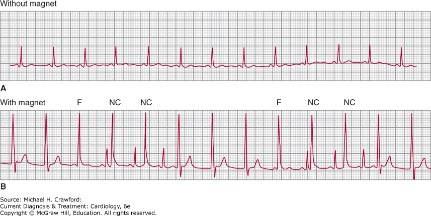
In the asynchronous mode of pacemaker function, no electrical signals are sensed, and the pulse generator delivers output pulses (nonprogrammable) without regard to any electrical activity occurring spontaneously within (or from outside) the heart (Figure 14–14). Because the native cardiac rhythm is not sensed, competitive rhythms (paced and native depolarizations) can result. Asynchronous pulse generators are no longer manufactured; however, the asynchronous pacing mode can be programmed. Asynchronous pacing also occurs whenever a magnet is placed over an implanted pulse generator to evaluate capture function. With a magnet in place, asynchronous pacing occurs at a manufacturer-specific rate; concomitant occurrence of the spontaneous rhythm result in iatrogenic parasystole (Figure 14–15). At the energy output of today’s pulse generators (1.5–7.5 V), induction of repetitive ventricular or atrial rhythms is usually not observed, although this possibility exists, especially if myocardial ischemia or electrolyte imbalance is present. It is important to recognize that with implantable cardioverter-defibrillators, placement of a magnet over the pulse generator will suspend tachyarrhythmia therapies (eg, shocks) but will not affect pacing system function.
Figure 14-14. Schematic illustrations of various pacing modes (see Permanent Pacing section for explanation of mode designations). A, atrial pacing stimulus; P, spontaneous P wave; R, spontaneous QRS; V, ventricular pacing stimulus.
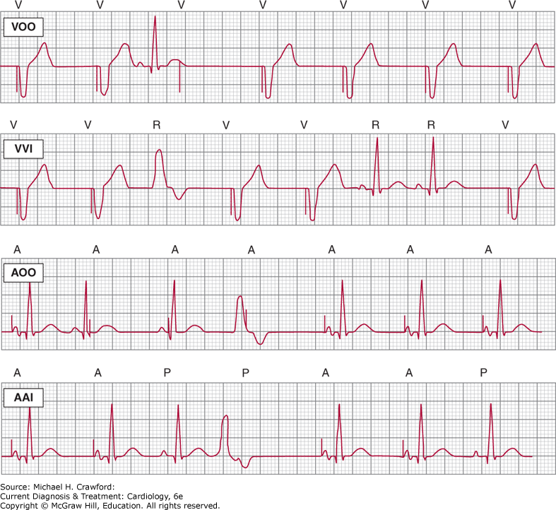
Figure 14-14.
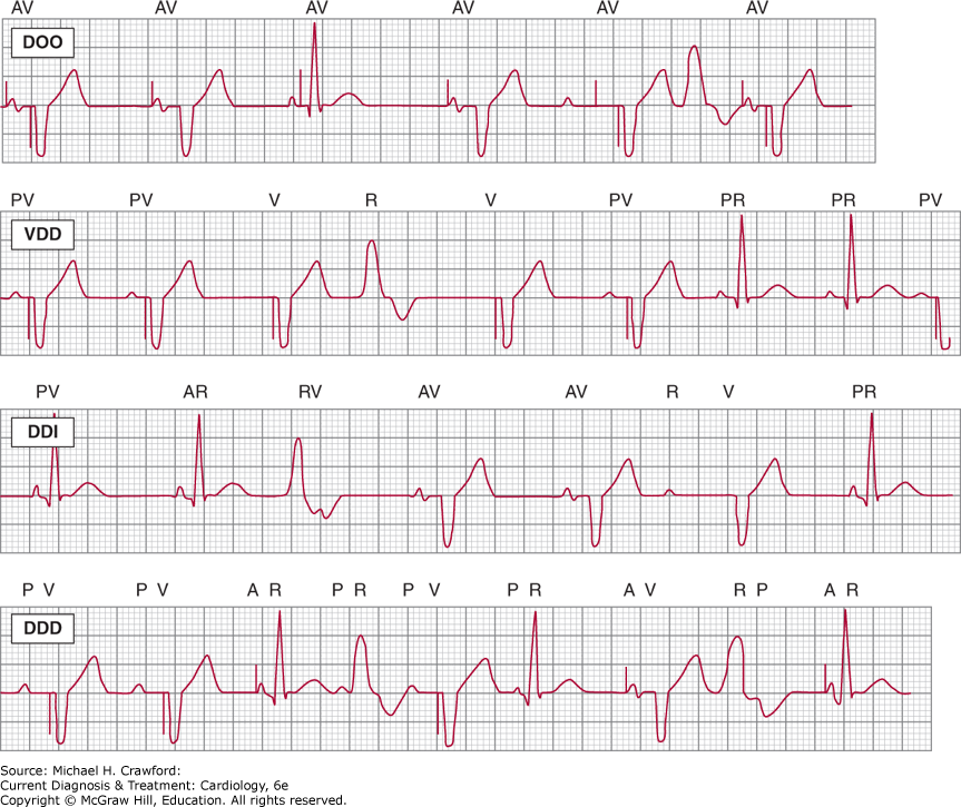
Figure 14-15. VVI pacing system. A: Normal sinus rhythm is present. Sensing function is presumed to be normal because no ventricular pacing artifacts are occurring. B: With a magnet in place over the pulse generator, ventricular pacing stimuli are emitted asynchronously, resulting in a rhythm that competes with the sinus rhythm. The large magnitude of the pacing artifacts indicates that the lead configuration is unipolar. The large unipolar stimulus obscures the resulting QRS complex; however, because T waves are present following some of these pacing stimuli, capture is confirmed. Both sensing and pacing functions are normal. F, true fusion complexes, with ventricular depolarization resulting from both sinus and paced impulses. NC, noncapture because of pacing stimuli falling in the refractory period of ventricular muscle; this has been referred to as “functional” noncapture.
(2) Single-Chamber Demand Pacing (Vvi[r], Aai[r])
Both sensing and pacing circuits are present in these units. When a spontaneous intracardiac signal is sensed, VVI and AAI pulse generators will inhibit their output and no pacemaker stimulus artifact will appear. Electrical signals sensed by demand pacemaker pulse generators can originate not only from the heart but also from the environment (eg, electrocautery, some cell phones, electronic article surveillance systems, tasers), from the patient (muscle potentials), or from the pacing system itself (lead fracture or insulation breaks). Such sensed signals may cause inhibition of output, leading to pauses in paced rhythm; this phenomenon is termed oversensing (Tables 14–9 and 14–10), a problem that can generally be corrected by noninvasive programming or, in the case of lead fracture or insulation break, by replacement of the lead. Current pulse generator design and programming capability have not only helped to reduce problems of oversensing but have also simplified their correction.
Table 14–9. Pacing System Malfunctions and Clues to Their Recognition
Undersensing Single-chamber systems ECG will show earlier-than-expected appearance of pacing-stimulus artifact Dual-chamber systems Atrial undersensing: Delivery of atrial pacing stimuli despite occurrence of spontaneous P waves; failure to track intrinsic atrial activity at the programmed AV interval Ventricular undersensing: Delivery of ventricular pacing stimuli despite occurrence of spontaneous QRS complexes Oversensing ECG will show inappropriate inhibition of atrial or ventricular output stimuli; oversensing in the atrial channel results in earlier-than-expected ventricular pacing stimuli (“triggering,” “tracking”) Noncapture Pacing stimuli not followed by atrial or ventricular depolarization (assuming muscle tissue is not refractory) Failure of output Absence of pacing stimulus outputs, with oversensing excluded |
AV, atrioventricular; ECG, electrocardiogram.
Table 14–10. Potential Causes of Pacemaker Oversensing
Electromagnetic interference Power transformers, power lines; welding equipment; running motors and alternators; chainsaws; household appliances such as electric shavers and hair dryers (unusual with today’s pulse generators); cell phones (some newer models); headphones and earbuds (if draped around neck); electric fences; metal-detector gates (older generation designs); electronic article surveillance systems; tasers; magnetic therapy products; transcutaneous nerve stimulators; therapeutic radiation; MRI; radiofrequency catheter ablation; cardioverting and defibrillating devices (external or implanted); electrocautery; electrocoagulation; diathermy; lithotripsy Physiologic intracardiac signals R-wave sensing (AAI1 systems), T-wave sensing (VVI1 systems), P-wave sensing (VVI systems) (unusual) Physiologic extracardiac signals Muscle potentials (myopotentials) (eg, diaphragm, pectoral) Signals generated within the pacing system Conductor-wire fracture causing a voltage transient Lead insulation defect Pulse generator component malfunction Afterpotential sensing of late portions of the pacing stimulus itself (unusual) Inappropriate programmed settings |
1 Pacemaker codes: A, atrium; I, inhibited; V, ventricle.
MRI, magnetic resonance imaging.
The capture function of a demand pulse generator cannot be evaluated if the patient’s spontaneous rhythm exceeds the programmed standby (base) rate of the generator. Applying a magnet over the pulse generator converts it to an asynchronous mode of function, and capture (stimulation) of the atria or ventricles by the pacemaker can be confirmed, provided that the pacing stimuli fall outside the refractory period of the cardiac tissue. Conversely, if the patient’s rhythm is continually paced, the sensing function of the pulse generator cannot be evaluated. Programming the device to a lower rate may allow the emergence of a spontaneous cardiac rhythm, which should then be sensed, resulting in inhibition of pacemaker output.
Continuous single-chamber ventricular pacing will result in AV dyssynchrony (unless the atrial rhythm is fibrillation). Although the symptoms attributable to bradycardia are alleviated through ventricular rate support from the pacemaker, these may be replaced by symptoms due to AV dyssynchrony, or “pacemaker syndrome.” Either single-chamber atrial pacing (with intact AV conduction) or dual-chamber pacing is a solution to avoid pacemaker syndrome.
(3) Single-Lead P-Synchronous Pacing (Vdd)
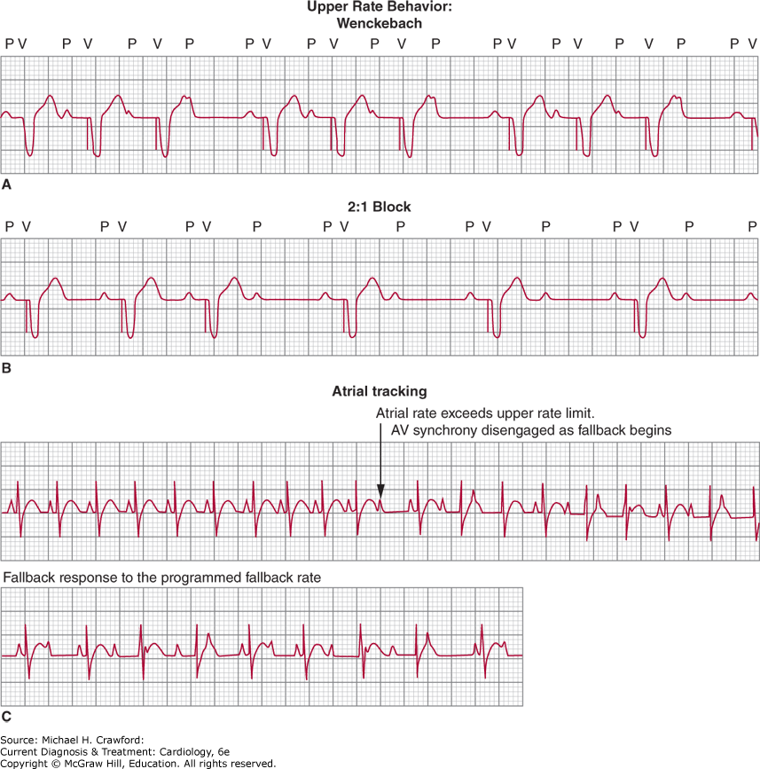
These are systems in which electrodes for both the atrium and the ventricle are located on a single lead. The lead is positioned in the right ventricle where the tip electrodes sense and pace the ventricle; atrial electrodes are located on the lead body, at the level of the atrium and are currently only capable of sensing. When the atrial electrode senses an electrical signal, a ventricular pacing stimulus is delivered after a programmable AV delay that corresponds to the PR interval. If a spontaneous QRS complex occurs, the ventricular output is inhibited. Tracking of the atrial rhythm in a 1:1 relationship allows the ventricular paced rate to change with the sinus rate. The programmed upper rate is the maximum ventricular paced rate that can occur in a 1:1 relationship to atrial activity and prevents rapid ventricular paced rates should the atrial rate become too fast. If the atrial rate exceeds the programmed upper rate limit, the paced ventricular rate can become irregular because of an electronic Wenckebach protection, can slow to one-half the programmed upper rate limit, or can fall back gradually until 1:1 tracking can resume. This last feature results in disengagement of the tracking function, which causes transient AV dyssynchrony (Figure 14–16).
Figure 14-16. Schematic illustration of responses from pulse generators at the atrial-driven programmed upper rate limit. The pacemaker will not allow the ventricular paced rate to exceed this upper rate (or “maximum tracking rate”). Atrial rhythms that can exceed the upper rate limit include sinus tachycardia, atrial tachycardia, atrial flutter and atrial fibrillation. The pacemaker-mediated tachycardia (see text) will also not exceed the programmed upper rate. A: Lengthening of the interval between the sensed P wave and the triggered ventricular-paced complex so as not to violate the upper rate limit (Wenckebach): the P wave that is not followed by a paced QRS complex falls in the refractory period of the atrial channel and is not sensed, resulting in absence (nondelivery) of the ventricular stimulus output. B: In 2:1 block, alternate P waves fall in the programmed atrial refractory period and are not sensed: they are not followed by a paced ventricular event. C: In “fallback,” the ventricular paced rate gradually slows once the programmed upper rate has been achieved. During the fallback period, tracking of the atrial rate is disengaged, and atrioventricular synchrony is no longer present. The ventricular paced rate will again track the atrial rate once the latter falls below the programmed upper rate. The fallback response avoids abrupt decreases in paced ventricular rate. Pacemakers that function in a rate-adaptive mode can have their sensor-based upper rate limit exceed the previously described atrial-based upper tracking limit.
If no atrial activity is sensed, as occurs in sinus bradycardia, most current VDD systems pace the ventricles on demand at the programmed base rate; atrial pacing does not occur. Thus, at slow atrial rates, the pacing system behaves as though it was a VVI system, and AV synchrony is lost (Figure 14–14). Although this pacing system seems ideal for patients with normal sinus rhythm and AV block, atrial bradycardia, which occurs commonly over ensuing years, either spontaneously or as a result of medications, makes VDD devices ultimately suboptimal for most patients, and they are rarely used today.
(4) Dual-Chamber Pacing (DDD[r])
These pacing systems are capable of sensing and pacing in both the atrium and the ventricle on demand (Figure 14–14). Therefore, they approach the physiology of normal AV conduction. The ability to sense retrograde atrial depolarizations can lead to ventricular stimulus delivery and ventricular pacing in response; if the paced ventricular depolarization travels retrograde to the atrium to depolarize it, the process can become repetitive. This event creates an artificial extra-AV-nodal bypass tract, causing a “pacemaker-mediated tachycardia.” Specific algorithms have been designed to terminate these tachycardias and are automatic once they have been programmed “on.”
Dual-chamber devices depend on a stable atrial rhythm for optimum function. Because of their potential for rapid paced ventricular rates, these systems should not be used with atrial arrhythmias such as permanent fibrillation or flutter, multifocal tachycardia, or refractory automatic tachycardia; unless catheter ablation can effectively treat the atrial arrhythmia (especially atrial flutter), single-chamber VVI(R) devices should be used instead.
If the atrial tachyarrhythmias are paroxysmal, however, a “mode switch” feature should be programmed “on” that automatically changes the mode from DDD(R) to either DDI(R) or VVI(R) modes when a rapid atrial rate is detected; this removes the ability to track the atrial rate as long as the atrial tachyarrhythmia persists (Figure 14–17). Some studies have shown that in patients with bradycardia, compared with ventricular pacing, atrial-based pacing reduces the incidence of atrial fibrillation.
Figure 14-17. Depiction of mode-switch operation of a dual-chamber pacemaker. In the initial portion of the rhythm strip, tracking of atrial fibrillation is occurring, resulting in a rapid paced ventricular rate. When the algorithm in the pacemaker recognizes the atrial tachyarrhythmia, automatic change of mode of function to VVIR takes place, terminating the rapid paced ventricular rate. On sensing restoration of a normal atrial rhythm, the device will automatically restore its dual-chamber mode of operation.
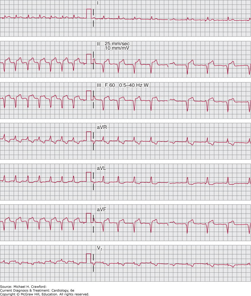
Right ventricular pacing has been recognized as a cause of dyssynchrony-mediated cardiomyopathy. This process is similar to what has been observed in patients with spontaneous LBBB, where abnormal electrical activation can initiate electrical remodeling that then leads to myocardial remodeling. Dyssynchrony-mediated cardiomyopathy can be reversed with cardiac resynchronization therapy (CRT) through biventricular pacing. In patients with preexisting cardiomyopathy, biventricular pacing can be considered at the time of pacemaker implant if ventricular pacing is deemed unavoidable. His bundle pacing is an alternative approach to right ventricular or biventricular pacing where the ventricular lead is affixed to the proximal intraventricular septum and the His bundle is directly activated; ventricular electrical activation then occurs in a more physiologic pattern via the His-Purkinje system. Ongoing clinical trial are evaluating the potential clinical benefit of His bundle pacing over right ventricular or biventricular pacing in both preventing and reversing dyssynchrony-mediated cardiomyopathy.
In patients who do not need continuous ventricular pacing, various parameters can be programmed to minimize unnecessary ventricular pacing. The AV delay can be programmed in most current pacemakers to automatically extend, allowing native AV conduction to occur as much as possible. There are also manufacturer-specific modes that maintain AAI(R) mode until AV block is detected, at which time they automatically switch to DDD(R) mode; AAI(R) mode is restored when the pacemaker detects resumption of native AV conduction.
The type of pacing system implanted is indicated on an identification card supplied to the patient by the manufacturer. It is important to note, however, that such information does not guarantee the operation of a particular mode of function, rate, or any parameter that can be programmed by the patient’s pacemaker physician. As pulse-generator design and function increase in complexity, it is best to assume that the pacemaker is performing normally until proved otherwise (there are, of course, malfunctions and “pseudo” malfunctions; these are addressed in the following sections). Similarly, ECGs in paced patients should be considered to reflect normal device function unless they are interpreted otherwise by personnel experienced in pacemaker ECG.
Rate-adaptive pacing systems are appropriate for patients with permanent atrial arrhythmias with slow ventricular response and for patients whose sinus node dysfunction prevents rate acceleration, but who would benefit from an increase in paced ventricular or atrial rates, respectively, in response to increases in metabolic demand. Current sensors measure body motion and acceleration, minute ventilation, QT interval, or intracardiac impedance. Leadless pacemakers also have rate-adaptive capability utilizing a multiaxis accelerometer that detects activity in the presence of cardiac motion. Changes within the sensor’s established parameters, designed to reflect physiologic needs, result in changes in paced rates. Sensor-based pacing rate depends on the individual sensor used, however; for example, if an activity sensor is being used, the paced rate can increase in response to body vibrations that are unrelated to actual physical activity, such as shivering or tremor. This can cause problems in hospitalized patients, especially those in intensive care units. Several manufacturers, therefore, currently incorporate two sensors into their pacemakers to confirm the need for appropriate changes in pacing rate. For example, the activity sensor input can be confirmed by a more physiologic sensor such as minute ventilation, resulting in a more specific and accurate response to the change in pacing rate for the change in metabolic need. Recognition of sensor-based pacing and changing pacing rates is necessary to avoid erroneous diagnoses of pacemaker malfunction.
B. Unipolar and Bipolar Pacing
Unipolar pacing systems have the cathode (stimulating electrode) in the heart and the anode at the pulse generator. The distance between the cathode and anode in these systems results in the inscription of large pacing artifacts whose direction (pacing-artifact axis) in the frontal plane points toward the anode in older analog ECG recorders, but not in contemporary digital recorders in which stimulus artifact amplitudes and axes vary due to digital sampling of the pacing stimulus.
Bipolar pacing systems have both lead electrodes within the heart, usually less than 1 cm apart, in either or both atrium and ventricle. Either the distal (tip) electrode or the proximal (ring) electrode of the lead can serve as the cathode. Because of the small interelectrode distance, the pacing artifacts are small and their direction in the frontal plane reflects the direction of current flow (Figure 14–18). It is common for the small pacing artifacts to be difficult to discern on ECGs and ECG monitoring strips; even computer-interpreted ECGs may fail to indicate that a pacemaker is present. Identification of paced (as opposed to spontaneous) P waves and QRS complexes must therefore be intentionally undertaken; often, magnet application with comparison of paced P and QRS morphologies with the initially recorded complexes is necessary to accomplish this.
Figure 14-18. Bipolar VVI pacing system. All QRS complexes are paced. Note the small magnitude of the pacing artifacts. The simultaneous recordings indicate that in some leads the pacing stimuli are virtually invisible.
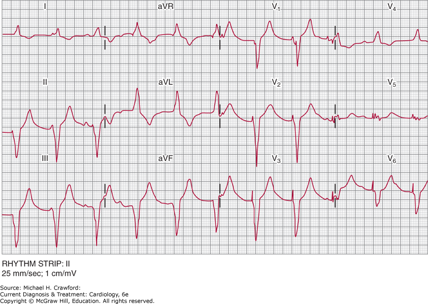
In sum, ECGs recorded on digital rather than analog machines can show marked variations in both amplitude and polarity of pacing artifacts. Because the digital equipment samples the pacing stimuli at specific time intervals and then recreates them on paper, the inscribed stimulus artifacts are not seen in real time. In some ECG leads, the pacing stimuli may not be visible at all, raising the questions of spontaneous wide QRS complex rhythms or even failure of pulse generator output. It is important to recognize this recording artifact in patients with pacemakers to avoid an erroneous diagnosis of pacemaker malfunction. It is equally important to document the morphology of paced complexes so that when the pacing stimuli cannot be seen, normal pacemaker function can be assumed until an accurate evaluation can be made.
Some permanent bipolar pacing systems offer lead polarity that can be programmed to unipolar; therefore, the presence of a bipolar lead on chest radiograph does not ensure bipolar lead function, and the ECG appearance of the pacing artifacts may differ from what is expected. That being said, most pacing systems today use bipolar leads and are programmed to function as bipolar leads unless there has been a revision undertaken for a specific reason.
C. Electrocardiographic Patterns of Paced Complexes
These patterns depend on how the myocardium is depolarized. Paced atrial complexes reflect the sequence of atrial activation initiated by the pacing impulse and thus, in part, the site of the pacing electrode(s). Because the atrial electrodes can be located in the atrial appendage or affixed to any portion of atrial tissue, paced P-wave morphologies and axes will vary.
Pacing from the right ventricular apex produces paced QRS complexes that have a LBBB configuration (reflecting right ventricular myocardial depolarization occurring before left ventricular depolarization) and a superior mean frontal plane axis (the apex of the heart is depolarized before the base; Figure 14–19). Paced QRS complexes usually have a duration of 120–180 ms; if they are substantially longer, intrinsic myocardial disease, hyperkalemia, or antiarrhythmic drug therapy (eg, flecainide, amiodarone) should be suspected.
Figure 14-19. Atrioventricular pacing at AV interval of 120 ms, with ventricular pacing from the area of the right ventricular apex, yielding superiorly directed paced QRS complexes with a left bundle branch block pattern. The paced P-wave morphology and axis are similarly determined by the location of the pacing lead tip.
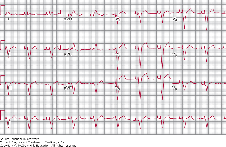
Pacing from the right ventricular outflow tract also results in QRS complexes that have a LBBB pattern, but the mean frontal plane axis is inferiorly directed (the base of the heart is depolarized before the apex). Occasionally, pacing from the interventricular septum can result in paced QRS complexes that show an indeterminate conduction delay pattern; they can even be narrow and relatively normal-appearing. This reflects almost simultaneous activation of both the right and left sides of the interventricular septum. Pacing from the His-bundle region can result in either normal-appearing narrow QRS complexes that reflect selective capture of the His bundle, or fusion complexes that are a combination of His bundle and right ventricular septal pacing.
Pacing from the left ventricular epicardium from electrodes positioned via the coronary sinus or placed directly at the time of cardiac surgery, produces paced QRS complexes having a RBBB pattern, reflecting left ventricular myocardial activation in advance of right ventricular activation. The mean frontal-plane QRS axis will depend on the location of the epicardial electrodes relative to each other (bipolar system) or to the pulse generator serving as anode (unipolar system).
Biventricular pacing can be recognized by tightly coupled double-pacing artifacts (Figure 14–20); biventricular pacing devices, however, can be programmed to deliver pacing in the left ventricle only, usually timed to coincide with native right ventricular activation, and the lack of double-pacing artifact does not exclude CRT. The resulting paced QRS complexes typically have a RBBB-like pattern since left ventricular pacing is usually programmed first, up to 80 ms earlier than right ventricular activation. The mean frontal plane axis will vary primarily with the location of the left ventricular electrode. Biventricular paced QRS complexes can be narrower than spontaneous QRS complexes, reflecting synchronized activation of left ventricular septum and free wall; electrical synchrony, however, does not necessarily correlate with mechanical synchrony, and a persistently wide biventricularly paced QRS complex does not predict failure of therapy. Because there are various programmable algorithms that trigger left ventricular or biventricular pacing when intrinsic ventricular activation is sensed, seemingly unusual responses to native conduction, rapidly conducted atrial fibrillation, and ventricular ectopy can be observed that require detailed knowledge of manufacturer-specific programming to properly decipher.
Figure 14-20. Leads II and V5 in patient with a biventricular pacing system, programmed with a VV timing set to LV first by 60 ms. Two distinct ventricular stimulus output artifacts are seen tightly coupled at the onset of the paced QRS complex, following a sensed P wave.
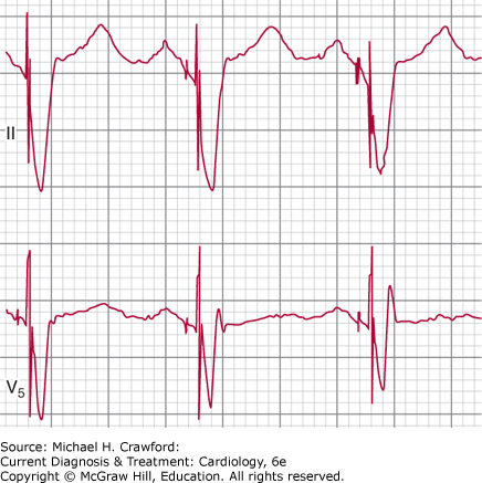
Spontaneous QRS complexes occurring in patients with pacemakers often show marked T-wave inversion (Figure 14–21). This phenomenon has been explained as “T-wave memory” or the persistence of abnormal repolarization “learned” by the myocardium during pacing. The ECG abnormality should not be interpreted as acute or chronic myocardial disease (including ischemia and infarction) in the absence of clinical correlations.
Figure 14-21. Twelve-lead electrocardiogram in patient with a DDD pacing system, temporarily programmed to a rate of 30 bpm to permit emergence of the native rhythm. The intrinsic rhythm is sinus with complete atrioventricular block and right bundle branch block. Because no pacing artifacts are occurring, sensing function is normal in both atrium and ventricle. The deeply inverted T waves in the inferior and precordial leads represent a nonspecific abnormality (T-wave memory) commonly observed when pacing is suddenly suspended; they do not represent myocardial injury.
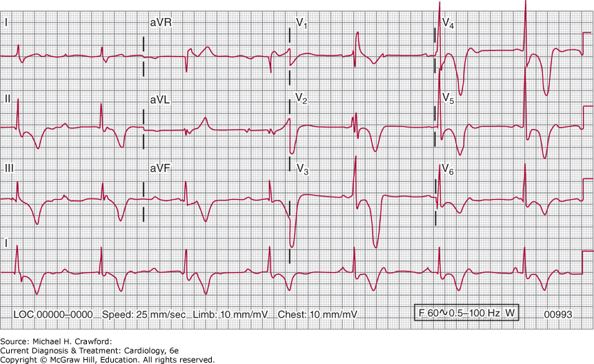
D. Pacemakers and Electromagnetic Interference
Electromagnetic interference (EMI) occurs when electrical or magnetic energy interferes with the normal function of a pacemaker. In general, EMI of pacemaker function is currently less of a problem than in previous years because of changes in the design of pacemakers, such as the use of titanium cases that are nonferromagnetic, the implementation of special filters or algorithms that distinguish EMI from intracardiac signals, and bipolar leads that have reduced the field of sensing to a few millimeters within the heart. Nonetheless, EMI can still occur, and understanding the potential effects of EMI on a pacemaker, as well as the potential sources of EMI, is important in the management of patients with pacemakers.
The most common effect of EMI is oversensing, or the sensing of unwanted electrical signal (Table 14–10). When oversensing occurs due to EMI, the environmental signal is sensed as intrinsic cardiac activity, and either inappropriate inhibition of pacing or unnecessary and unwanted triggered pacing occurs, depending on the pacemaker type and programmed mode of function. In patients who are pacemaker dependent (no intrinsic heart rate > 30 bpm or symptoms at lower-than-programmed rates), inhibition of pacing can result in dizziness, weakness, or syncope. With a dual-chamber pacemaker programmed in a synchronized mode such as DDD(R), patients can experience palpitations as triggered ventricular pacing occurs from electrical signals detected by the atrial lead. Rarely, EMI can also affect certain types of rate-adaptive algorithms, induce the device into reverting to a “reset mode” (a safety mode in some devices that paces at high output at a specific rate), or result in pulse generator damage.
In general, it is uncommon for EMI to cause serious harm, but it should be avoided in patients who are pacemaker dependent. Patients should be made aware of whether or not they are pacemaker dependent and of the potential causes of EMI. Sources of EMI in the typical surrounding environment are usually of low intensity, and EMI occurs only when the source is within inches of the pacemaker system. Although actual interference with cell phones is increasingly rare, certain phones that employ magnets have been found to cause interference and are advised to be kept at least 6 inches from the pacemaker generator. Interactions at airport screening are usually too transient to interfere with normal pacemaker function. Patients with pacemakers should know not to linger in the vicinity of any electronic surveillance equipment.
EMI can occur in a variety of medical settings (Table 14–10). The effect of unipolar electrocautery during surgery is the most common medical source of EMI. All patients with pacemakers undergoing surgery should have preoperative assessment of pacemaker dependency and pacemaker function, including the function and rate with magnet application. Reprogramming of the pacemaker to an asynchronous nonadaptive mode at rates higher than the patient’s spontaneous rate can be recommended if the site of surgery is close enough to the pacing system. Other sources of EMI in the hospital include ionizing radiation (which can reset or damage the system), transcutaneous electrical nerve stimulation, radiofrequency ablation, external cardioversion or defibrillation, and lithotripsy, and therapy-specific precautions are necessary.
E. Pacemakers and Magnetic Resonance Imaging
In past years, magnetic resonance imaging (MRI) has been contraindicated in patients with pacemakers. This is based on observed deleterious effects that strong magnetic fields can have on pacemakers, and on a handful of reported deaths not definitively associated with MRI scanning. Potential effects range from activation of rate-adaptive sensors causing rapid pacing rates, to reversion of pulse generators to default mode and settings. There is also the concern for electromagnetic current induction within leads that can give rise to heating at the lead tip-tissue interface and result in acute capture threshold increase; in a pacemaker-dependent patient, critical loss of capture could then ensue.
Pacemakers and leads that are approved by the U.S. Food and Drug Administration for use with MRI are now available from all major manufacturers, and should be used if there are underlying conditions that will likely require future MRI scans (eg, history of cancer, orthopedic problems, neurologic abnormalities). MRI compatibility is currently conditional only under specific pacing system and MRI scanning settings. When performing an MRI scan in a patient with an MRI-conditional pacing system, a specific protocol should be followed to ensure patient safety. Capture thresholds and lead impedances must be verified prior to scanning. The presence of a non-MRI-conditional lead, a lead adapter or extender, or any abandoned lead precludes the use of MRI scanning. After scanning, pacing system function must be reevaluated and reprogramed as necessary.
There are instances where the benefits of MRI scanning (eg, early detection of cancer, imaging of the brain) need to be weighed against the potential risks to the patient with a non-MRI-conditional pacemaker system. Protocols have been established by several institutions that allow for non–pacemaker-dependent patients to undergo MRI scanning under close observation after making temporary programming changes that will minimize interaction with the magnetic field. Pacemakers implanted in the last 15 years have advanced EMI protection, even if not MRI conditional, that decreases the likelihood of encountering a problem.
B. Pacing System Malfunctions
Pacing system malfunctions fall into four general categories: (1) undersensing (mistakenly referred to as “failure” to sense); (2) oversensing; (3) noncapture (mistakenly referred to as “failure” to capture); and (4) failure of output.
Undersensing of cardiac electrical signals because of poor intrinsic signal quality does not represent sensing failure as such, but rather the inability to detect the suboptimal signal itself; undersensed P waves and QRS complexes are not rare. Premature ventricular complexes (Table 14–9; Figure 14–22) generate suboptimal signals because they originate from within the myocardium, away from the normal conduction apparatus; they can occur in patients without structural heart disease, during acute myocardial ischemia and infarction, or as a result of drug toxicity and electrolyte imbalance (Table 14–11). Undersensed P waves can be due to changes in atrial volume, ectopic atrial rhythms, retrograde atrial depolarizations, or inappropriate programmed settings. Undersensing of spontaneous complexes and consequent failure to inhibit output results in the delivery of an earlier-than-expected pacing stimulus, which can, on occasion, induce repetitive rhythms.
Table 14–11. Potential Causes of Pacemaker Undersensing
Poor myocardial voltage signals Change in conduction pattern (ectopy, new bundle branch block) Electrolyte or metabolic abnormalities (hyperkalemia, acidosis) Medications (flecainide, amiodarone) Myocardial ischemia or infarction (scar) Lead or pacing system problem Poor lead positioning at the time of implant Lead displacement Lead tip-tissue fibrosis Conductor-wire fracture causing non-transmission of signal Lead insulation defect Inappropriate programmed settings |
Figure 14-22. Undersensing of spontaneous ventricular complexes in a patient with a VVI pacing system. Because the signal quality of depolarization originating in ventricular tissue is often poor, this is not uncommon. Repetitive ventricular beating induced by the stimulus-on-ST complex is, however, rare in stable patients.
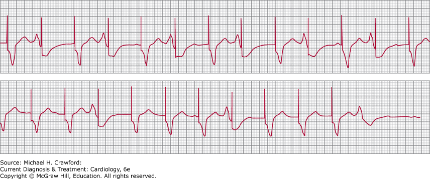
Ventricular pacing artifacts can sometimes occur after the onset of spontaneous QRS complexes that have a RBBB configuration, raising concern of undersensing. This happens because of delay in conduction in the right bundle branch: the wavefront of ventricular depolarization does not reach the lead electrode in the right ventricle (especially the apex) in time to inhibit the output of the pacing stimulus. This phenomenon of stimulus delivery within a QRS complex, called “pseudofusion” (as opposed to true fusion), may also be observed in patients with inferior and right ventricular myocardial infarction and is probably due to the conduction delay resulting from ventricular scarring. The same principles apply to patients who have a left ventricular epicardial electrode and either underlying LBBB or ventricular scarring and to patients who have a right atrial electrode and an intra-atrial conduction delay. Undersensing in these cases is due to intrinsic conduction system disease rather than to a malfunctioning unit. The problem is managed by extending the programmed AV delay (in the case of ventricular pseudofusion), programming a higher sensitivity, or if necessary, increasing the pacing rate to overdrive the native rhythm.
Oversensing refers to sensing of unwanted electrical signals such as T waves, myopotentials, and environmental signals (eg, electrocautery; Table 14–10). Programming the pulse generator to sense only electrical signals of larger magnitude will often solve the problem. When a programmer is not immediately available, placing a magnet over the pulse generator will temporarily eliminate the oversensing by converting the generator to a non-sensing asynchronous mode of function. Because competitive rhythms with the magnet in place can induce ventricular tachyarrhythmias, these patients should be in a monitored unit.
Noncapture exists when pacing stimuli do not depolarize nonrefractory myocardium (Figure 14–23; Table 14–12). This condition may result from poor electrode position; a subthreshold programmed output; output reduction due to battery depletion; or an increase in myocardial stimulation threshold that can results from acute myocardial infarction, drug effect, electrolyte imbalance, cardiopulmonary resuscitation, or fibrosis at the electrode-tissue interface. Noncapture can be managed by noninvasive programming of the pulse generator’s energy output (voltage and pulse duration), surgical repositioning of the lead, or generator exchange, depending on the underlying problem.
Table 14–12. Causes and Management of Pacemaker Noncapture
Tissue refractoriness: Verify capture during temporal opportunity Lead dislodgement: Reposition lead, or program lead polarity Increase in myocardial stimulation threshold: Program higher energy output; treat underlying cause if possible Lead-insulation break: Repair or replace lead; unipolarize lead Conductor-wire fracture: Replace lead Inappropriately low programmed output: Program higher output Generator end of life: Replace generator |
Figure 14-23. Noncapture and undersensing in a patient following cardiac arrest; a temporary transvenous pacing system had been placed in the right ventricular apex. The QRS complexes are spontaneous and occur at a severely slow rate; they do not follow pacing stimuli.
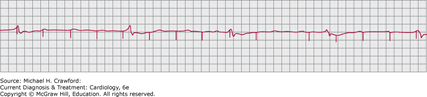
The difference between noncapture (stimulus artifact is present) and failure of output (lack of stimulus output when such output is expected and indicated) should be recognized. If the pacing stimulus has not been delivered (Table 14–13), capture cannot be ascertained. Applying a magnet will aid in determining the cause for the lack of stimulus output. Asynchronous pacing will result with magnet application if the lack of pacing stimulus output results from inhibition due to oversensing. If there is a true problem with delivery of a stimulus output, no stimulus output and therefore no paced complexes will be seen despite magnet application. The main causes of failure of output are battery depletion and pulse generator component failure. This is to be distinguished from the situation when pulse generator output is occurring normally but the current is not reaching body tissues to depolarize it, due to lead fracture or insulation break, and loose set screw (loss of connection between the lead connector pin and the pulse generator). Management of pacemaker failure of output will require replacement of the pulse generator, whereas lead problems usually require lead replacement, and loose set screws are addressed merely by restoring a good connection between the lead connector pin and the generator.
Table 14–13. Causes of Absence of Pacing Stimulus Output and Response to Magnet Application
| Cause | Response to Magnet |
|---|
| Normal inhibition by P waves and QRS complexes | Pacing stimuli will be delivered asynchronously |
| Oversensing | Pacing stimuli will be delivered asynchronously |
| Lead fracture | Pacing stimuli may not be seen if the break in the wire is complete (current does not reach body tissues); may be seen as multiples of a basing pacing rate, or may be seen intermittently (make–break circuit); may have variable amplitude |
| Lead-generator disconnection or improper connection | Same as for lead fracture |
| Battery failure (end of life) | Pacing stimuli at slow rate, no visible pacing stimuli, noncapture, undersensing |
| Battery component failure | Variable response |
C. Assessment of Pacing System Function
All patients undergoing comprehensive pacing system assessment should have a 12-lead ECG, with and without a magnet applied, to allow identification of spontaneous (where present), purely paced, and fusion P waves and QRS complexes, as well as sensing and pacing functions in both atria and ventricles. The (nonprogrammable) pacing rate with a magnet in place is not the same as the programmed rate, as indicated earlier, and the mode of function with the magnet in place may differ from the programmed mode (eg, a DDD system may have a magnet mode that is VOO, although this is currently a rare event; Figure 14–24). The magnet mode, rate, and AV interval for each device are manufacturer and model specific and may vary, sometimes with stimuli delivered at one rate and AV interval, followed by another rate and AV interval.
Figure 14-24. A: Atrioventricular sequential pacing. The large magnitude of the pacing artifacts indicates unipolar pacing in both chambers. Because atrial pacing stimuli are followed by P waves, and ventricular stimuli are followed by QRS complexes, pacing function is normal in both chambers. Sensing function cannot be evaluated because spontaneous P waves and QRS complexes are not occurring. B: Twelve-lead electrocardiogram, recorded with magnet in place. The mode of function is VOO (asynchronous ventricular pacing) at 85 bpm.
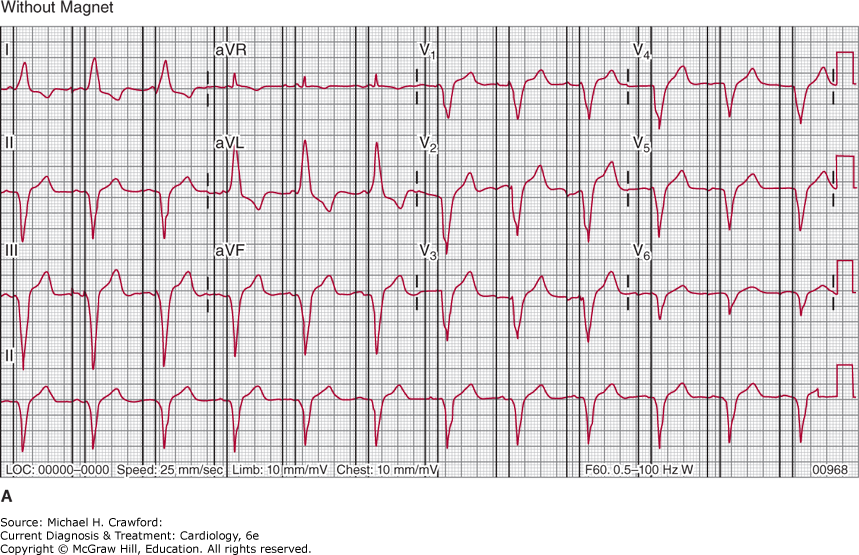
Figure 14-24.
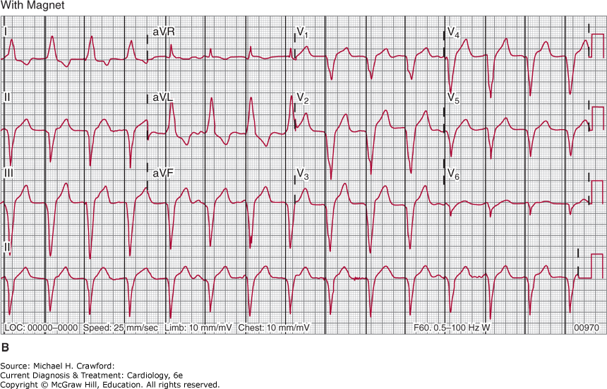
In addition, all patients should have highly penetrated posteroanterior and lateral chest radiographs to assess the leads and, when possible, to identify the pacemaker’s manufacturer and model number. The number and type (unipolar, bipolar, MRI conditional) of leads can be ascertained, as well as the positions of the lead tips and pulse generator. Lead tips lying outside the cardiac silhouette suggest the possibility of myocardial perforation. Occasionally, lead insulation degradation, wire fracture, or improper connections between the lead and pulse generator can be seen. Smartphone applications are now available that can identify the manufacturer of the pulse generator by analyzing the chest radiograph.
More sophisticated evaluation techniques, such as interrogation of the programmed parameters of the pulse generator, sensing and pacing threshold determination, and recording of intracardiac electrograms, can be necessary to detect and then determine the cause of pacemaker malfunction; these evaluations should be performed by a pacemaker specialist.
EpsteinAE, DiMarcoJP, EllenbogenKA,et al. ACC/AHA/HRS 2008 guidelines for device-based therapy of cardiac rhythm abnormalities. Circulation. 2008;117:e350e408. 18483207
GillisAM, RussoAM, EllenbogenKA,et al. HRS/ACCF expert consensus statement on pacemaker device and mode selection. Heart Rhythm.2012;9:13441365. 22858114
KusumotoFM, SchoenfeldMH, BarrettC,et al. 2018 ACC/AHA/HRS guideline on the evaluation and management of patients with bradycardia and cardiac conduction delay. Circulation.2019;140:e382e482. 30586772
NazarianS, HansfordR, RahseparAR,et al. Safety of magnetic resonance imaging in patients with cardiac devices. N Engl J Med.2017;377:25552564. 29281579